audi Workshop Repair Guides

Audi A3 Workshop Service and Auto Repair Manuals

Checking compression > < Removing and installing cylinder head
Removing and installing intake manifold
Removing
  Note
t  The following description is for removal and installation on vehicles with secondary air system. Some operations may not be required for earlier vehicles.
t  All cable ties which are released or cut open when removing must be fitted in the same position when installing.
–  Note (if necessary obtain) code on vehicles with coded radio / radio and navigation system (RNS).
–  Disconnect earth wire at battery with ignition switched off.
   
–  Take off engine cover panel -arrows-.
  A10-0397
–  Remove cover in front of intake manifold -arrows-.
  A10-0398
–  Detach pipe for secondary air system from brackets on engine -arrows-.
  A10-0914
–  Remove bolts -2- and -3- and detach bracket for dipstick guide tube -4-.
–  Unplug connectors -1- for turbocharger air recirculation valve -N249- and secondary air inlet valve -N112- on underside of retainer for electrical change-over valves.
–  Detach vacuum hose going to electrical change-over valves from intake manifold.
  A10-0413
–  Unbolt support -1- for intake manifold from intake manifold.
–  Detach vacuum hose -2-.
  A15-0638
Vehicles with hoses routed according to version 1:
–  Detach vacuum line -arrow- going to brake servo at intake manifold.
  A10-0926
Vehicles with hoses routed according to version 2:
–  Detach vacuum line -arrow- going to brake servo.
  A10-1155
All models:
–  Unplug electrical connectors -1- at intake air temperature sender -G42- and -4- at throttle valve module -J338- (bottom).
–  Detach vacuum line -3- leading to activated charcoal filter and air intake hose -2- from throttle valve module -J338-.
  A10-0401
Vehicles with throttle cable:
–  Disengage nipple -1- on end of throttle cable from cable cam.
–  Pull grooved section of throttle cable sheath -4- out of rubber grommet -2- at support bracket -5-.
  Note
Retaining clip -3- remains connected.
  A20-0400
All models:
–  Unplug electrical connector -arrow- at Hall sender -G40-.
  A15-0128
–  Unplug electrical connectors -1- on injectors.
–  Unclip retaining strip from fuel rail -2-.
  A15-0304
  WARNING
The fuel system is pressurised. Before opening the system place a clean cloth around the connection. Then dissipate pressure by carefully unfastening the connection.
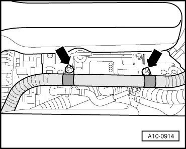
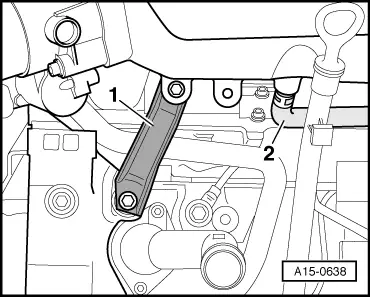
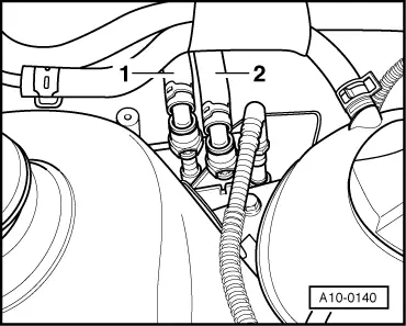
–  Disconnect fuel supply pipe -1- and fuel return pipe -2- by pressing release tabs.
–  Move fuel supply pipe and fuel return pipe clear.
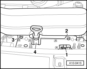
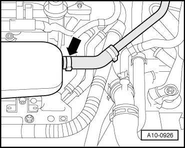
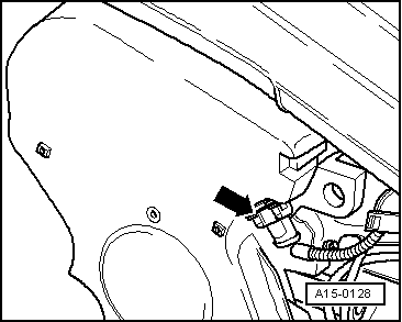
–  Disconnect crankcase breather hose from T-piece.
–  Pull out oil dipstick.
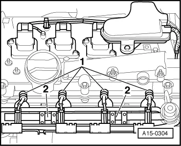
–  Unbolt and remove intake manifold from cylinder head.
  Note
Block off intake ports in cylinder head with clean cloths.
Installing
Installation is carried out in the reverse order; note the following:
  Note
t  Renew seals and gaskets.
t  Hose connections and hoses for charge air system must be free of oil and grease before assembly.
t  Secure all hose connections with the correct type of hose clips (same as original equipment) → Parts catalogue.
Vehicles with throttle cable:
–  Adjust throttle cable.
All models:
  Note
t  When the battery is reconnected, please ensure that the vehicle equipment (e.g. radio, radio/navigation system, clock, electric window lifters) is activated as described in the operating instructions.
t  For further operations after reconnecting power supply, refer to → Rep. Gr.24.
Tightening torques
  A10-0140
ComponentNm
Intake manifold to cylinder head10
Support for intake manifold to:Intake manifold20
Bracket45
Fuel rail to intake manifold10
Hose clips for air hoses3.5


Checking compression > < Removing and installing cylinder head