audi Workshop Repair Guides

Audi Workshop Service and Repair Manuals

Adjusting assembly mountings > < Securing engine to assembly stand
Installing engine
Installing engine
  Note
t  On assembly, renew oil seals and gaskets as well as self-locking nuts and bolts that are tightened by turning through to a specified angle.
t  Hose connections and hoses for charge air system must be free of oil and grease before assembly.
t  Secure all hose connections with the correct type of hose clips (same as original equipment) → Parts catalogue.
t  Fit all cable ties in the original positions when installing.
–  Check whether dowel sleeves for centring the engine/gearbox assembly are fitted in the cylinder block; install dowel sleeves if necessary.
   
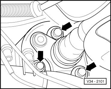
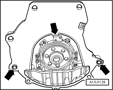
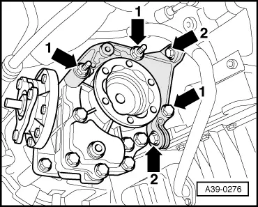
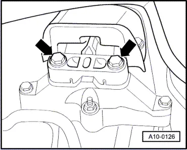
–  Engage intermediate plate on sealing flange and slip onto dowel sleeves -arrows-.
–  Check that clutch plate is correctly centred.
–  Check clutch release bearing for wear, renew if necessary.
–  Lightly grease clutch release bearing, release bearing guide sleeve and splines on input shaft with grease for clutch plate splines -G 000 100-.
  Note
t  Tightening torques apply only to lightly greased, oiled, phosphated or black-finished nuts and bolts.
t  Additional lubricant such as engine oil or gearbox oil may be used, but do not use lubricant containing graphite.
t  Do not use degreased parts.
t  Tolerance for tightening torques ± 15 %.
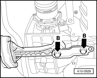
–  Fit bracket for bevel box before fitting engine/gearbox securing bolts.
–  Use new securing bolts.
  A10-0129
Securing engine to gearbox
  A37-0214
ItemBolt 2Nm
1, 2 1)M12x5580
3 1), 4 1)M12x16580
5M10x10540
6, 7M10x5040
8M12x7080
ADowel sleeves for centralising
l  1) Bolt with M8 stud
l  2) Renew bolts.

   
–  Push in small cover plate -2- for flywheel behind bevel box in such a way that lug at bottom engages into cylinder block and secure with bolt -1-.
  A34-0234
–  Fit bolts of bevel box bracket. Note tightening sequence:
  A39-0276
1.  Initially tighten bolts -arrow 1- to 3 Nm.
2.  Tighten bolts -arrow 2- to 35 Nm.
3.  Tighten bolts -arrow 1- to 45 Nm.

   
–  Guide engine/gearbox assembly into the body.
–  Tighten bolts securing engine mounting to engine support -arrows- initially hand-tight.
  A10-0125
–  Tighten bolts securing gearbox mounting to gearbox support -arrows- initially hand-tight.
–  Use new securing bolts.
  Note
The bolts are tightened to final torque only after adjusting the engine mountings → Chapter.
–  Remove engine bracket -T10012- from engine.
–  Bolt drive shafts to flange shafts of gearbox → Rep. Gr.40.
  Note
Drive shafts must be installed prior to further assembly.
–  Secure coupling rod to anti-roll bar → Rep. Gr.40.
  A10-0126
–  Secure pendulum support at gearbox -arrows B-.
–  Use new securing bolts.
  A10-0928
  Caution
Avoid damaging the seal -arrow- in the propshaft flange when installing. If a seal is damaged the propshaft must be renewed.
–  Push engine/gearbox assembly towards bulkhead; the journal of the bevel box must be simultaneously inserted horizontally and carefully into the flange of the propshaft.
  V39-1817
–  Secure pendulum support to subframe -arrows A-.
–  Use new securing bolts.
  N34-0887
–  Secure propshaft with flexible coupling to bevel box -arrows- → Rep. Gr.39.
–  Install catalytic converter and front exhaust pipe → Chapter.
–  Install exhaust system and align it free of stress → Chapter.
–  Install cross piece; note marking “L” or “Links” for left side of vehicle.
–  Use new securing bolts.
–  Knock back bushes for securing bolts slightly to facilitate installation of power steering pump and air conditioner compressor.
–  Install power steering pump → Rep. Gr.48.
–  Install secondary air pump → Chapter.
–  Install air conditioner compressor → Rep. Gr.87.
  V34-2101
–  Push the hydraulic line -1- for clutch slave cylinder into the hose connector and lock it with the catch.
  Caution
The clutch pedal must not be depressed prior to bleeding the clutch system.
–  Detach hose clamp -3094-.
–  Bleed clutch hydraulics → Rep. Gr.30.
Remaining installation steps are carried out in reverse sequence; note the following:
–  Install cable support bracket and selector cables → Rep. Gr.34.
–  Install poly V-belt → Chapter.
–  Adjust assembly mountings → Chapter.
–  Connect vacuum hoses → Chapter.
–  Install cross piece for suspension strut → Rep. Gr.40.
–  Electrical connections and routing → Current flow diagrams, Electrical fault finding and Fitting locations.
  Note
t  When the battery is reconnected, please ensure that the vehicle equipment (e.g. radio, radio/navigation system, clock, electric window lifters) is activated as described in the operating instructions.
t  For further operations after reconnecting power supply, refer to → Rep. Gr.24.
–  Check oil level → Chapter.
–  Fill cooling system → Anchor.
  Note
t  Drained-off coolant may only be used again if the original cylinder head and cylinder block are re-installed.
t  Contaminated or dirty coolant must not be used again.
  Caution
Never use battery charging equipment for boost starting. There is danger of damaging the vehicle's control units.
Tightening torques
  A10-0937
ComponentNm
Bolts/nutsM69
M820
M1045
M1265
Except for the following: 
Radiator cowl to radiator10
Pendulum support to:Gearbox40 + 90° 1)2)
Subframe20 + 90° 1)2)
Drive shaft heat shield to bevel box25
Rear cross piece to subframe30 + 90° 1)2)3)
Connecting pipe for charge air coolers to longitudinal member20
Hose clips for air hoses3.5
l  1) Renew bolts.
l  2) 90° = one quarter turn.
l  3) Install using locking fluid; for locking fluid refer to → Parts catalogue.


Adjusting assembly mountings > < Securing engine to assembly stand