
A3 Mk1
| Toothed belt drive - exploded view of components |

| 1 - | 10 Nm |
| q | Install using locking fluid; for locking fluid refer to → Parts catalogue |
| 2 - | Toothed belt cover (centre) |
| 3 - | Engine support |
| q | Removing and installing → Chapter „Removing and installing toothed belt“ |
| 4 - | 45 Nm |
| q | Observe the tightening sequence → Anchor |
| 5 - | Toothed belt cover (top) |
| 6 - | 23 Nm |
| 7 - | Washer |
| 8 - | Semi-automatic tensioning roller |
| q | Checking → Chapter |
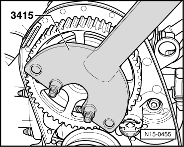
| 9 - | 100 Nm |
| q | Use counterhold tool -3415- to loosen and tighten → Fig. |
| 10 - | Camshaft sprocket |
| q | With sender wheel for Hall sender -G40- |
| q | Removing and installing → Chapter „Removing toothed belt from camshaft sprocket“ |
| q | Installation position fixed by Woodruff key → Item |
| 11 - | 10 Nm |
| q | Install using locking fluid; for locking fluid refer to → Parts catalogue |
| 12 - | 23 Nm |
| q | Install using locking fluid; for locking fluid refer to → Parts catalogue |
| 13 - | Toothed belt cover (rear) |
| 14 - | Woodruff key |
| q | Check for firm attachment |
| 15 - | O-ring |
| q | Renew |
| 16 - | Coolant pump |
| q | Removing and installing → Chapter |
| 17 - | 15 Nm |
| 18 - | Crankshaft toothed belt sprocket |
| q | Contact surface between sprocket and crankshaft must be free of oil |
| q | Can only be installed in one position |
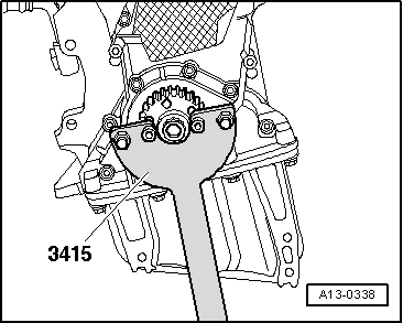
| 19 - | 90 Nm + 90° (1/4 turn) further |
| q | Renew |
| q | Do not lubricate with oil |
| q | Use counterhold tool -3415- when loosening and tightening |
| q | Fit counterhold tool -3415- → Fig. |
| 20 - | Toothed belt |
| q | Before removing, mark direction of rotation with chalk or felt-tipped pen. If the belt runs in the opposite direction when it is refitted, this can cause breakage. |
| q | Check for wear |
| q | Removing → Chapter |
| q | Installing (adjusting valve timing) → Anchor |
| q | Detaching from camshaft sprocket → Chapter |
| 21 - | Toothed belt cover (bottom) |
| q | Unbolt crankshaft pulley to remove |
| 22 - | 10 Nm |
| q | Install using locking fluid; for locking fluid refer to → Parts catalogue |
|
|
|
|