audi Workshop Repair Guides

Audi Workshop Service and Repair Manuals

Adjusting engine mountings > < Attaching engine to engine stand
4-Cylinder engine (5-valve), Mechanics
Removing and installing engine
Installing

Special tools and workshop equipment required

  • ◆ Depth gauge (for vehicles with automatic gearbox)

Work sequence

  • ● Engine mounted on engine bracket T10012.

Installation is carried out in the reverse sequence, when doing this note the following:

Notes:

  • ◆ All cable ties which are opened or cut open on removal must be replaced in the same position when installing.
  • ◆ Secure all hose connections with the correct hose clips (same as original equipment)

=> Parts catalogue

  • ◆ When performing repairs, renew self-locking nuts and bolts.
  • ◆ Renew self-locking nuts and bolts which have a specified tightening angle as well as seals and gaskets.
  • ‒ Check whether the dowel sleeves for centralising engine/gearbox are in the cylinder block, install if necessary.
 
A10-0129
  • ‒ → Engage intermediate plate on sealing flange, and press onto dowel sleeves -arrows-.

Vehicles with manual gearbox

  • ‒ Make sure that clutch plate is properly centred.
  • ‒ Check clutch release bearing for wear, renew if necessary.
  • ‒ Lightly grease clutch release bearing, release bearing guide sleeve and splines on input shaft with G 000 100.
  • ‒ Secure gearbox to engine.

Notes:

  • ◆ The tightening torques listed on this page apply only to lightly greased, oiled, phosphated, or black-finished nuts and bolts.
  • ◆ Additional lubricant such as engine or gearbox oil may be used, but do not use graphite lubricant.
  • ◆ Do not use degreased parts.
  • ◆ Tolerance for tightening torques is ±15%.
 
A37-0214

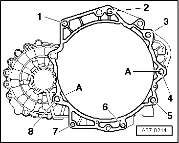
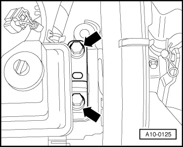
→ Engine/gearbox mountings (manual gearbox)

Item

Bolt

Nm

1, 2 1), 8

M12 x 55

80

3 1), 4

M12 x 150

80

5 ... 7

M10 x 50

45

    1)    Bolt with M8 stud

A: centering sleeves

 
A34-0234
  • ‒ → Slide in cover plate -2- so that bottom lug engages on cylinder block, and secure at the top with bolt -1-.
 
A32-0007

Vehicles with automatic gearbox

  • ‒ To secure the torque converter on the drive plate only use the correct nuts as specified in the parts catalogue.

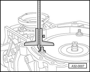
=> Parts catalogue

→ If the torque converter is correctly installed, the depth between the contact faces at the bottom of the studs on the torque converter and the contact surface of the torque converter bell housing is about 22 mm.

If the torque converter is not fully inserted, this distance is about 10 mm.

Important!
If the torque converter is incorrectly inserted, the driver of the torque converter or the ATF pump will be severely damaged when the gearbox is attached to the engine.
 
A37-0201
  • ‒ → Before installing engine, rotate torque converter and drive plate so that one hole and one stud are level with the opening in the torque converter cover.
  • ‒ Bolt gearbox to engine.
  • ‒ Tighten torque converter nuts with special tool Matra V/175.

Notes:

  • ◆ The tightening torques listed on this page apply only to lightly greased, oiled, phosphated, or black-finished nuts and bolts.
  • ◆ Additional lubricant such as engine or gearbox oil may be used, but do not use graphite lubricant.
  • ◆ Do not use degreased parts.
  • ◆ Tolerance for tightening torques is ±15%.
 
A37-0214

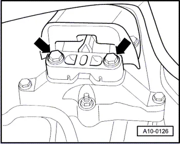
→ Engine/gearbox mountings (automatics)

Item

Bolt

Nm

1, 2 1)

M12 x 65

80

3 1), 4 1)

M12 x 180

80

5 ... 7

M10 x 50

45

8

M12 x 80

80

    1)    Bolt with M8 stud

A: centering sleeves

 
A10-0125

All models

  • ‒ Guide engine/gearbox assembly into engine compartment.
  • ‒ → Screw in and hand-tighten the bolts -arrows- connecting the engine support with the engine console ...

 
A10-0126
  • ‒ → ... and the bolts connecting the gearbox support with the gearbox console.
  • ‒ Use new bolts for securing.

Note:

The bolts are only tightened to their final specified torque settings when the engine mountings are adjusted .

  • ‒ Remove engine bracket T10012 from the engine.
  • ‒ Install drive shafts:

=> Running gear, Front-wheel drive and four-wheel drive; Repair group 40

Note:

The drive shafts must be installed before doing any more assembly work.

 
N34-0712
  • ‒ → Secure pendulum support -arrow B- first to the gearbox and then to the subframe -arrow A-.
  • ‒ Use new bolts for securing.
  • ‒ Install the exhaust system and align it stress-free => Page 26-18.
  • ‒ To ease the installation of the vane pump and the air conditioner compressor, knock back the sleeves for the holding bolts slightly.
  • ‒ Install the vane pump and the air conditioner compressor => Page 13-4.

Vehicles with manual gearbox

  • ‒ Install hydraulic clutch slave cylinder:

=> 5-Speed manual gearbox 02J; Repair group 30; Servicing clutch release mechanism

 
N34-0719
  • ‒ → Fit gearbox brace (arrows -A-) to gearbox.
  • ‒ Attach selector cables to gearbox and adjust:

=> 5-Speed manual gearbox 02J; Repair group 34; Servicing selector mechanism; Removing and installing selector cables

All vehicles:

The remaining installation steps are carried out in the reverse sequence.

  • ‒ Install ribbed belt .
  • ‒ Adjust engine mountings => Page 10-46.

Vehicles with throttle cable:

  • ‒ Adjust throttle cable:

=> Fuel supply system - Petrol engines; Repair group 20; Servicing accelerator mechanism - Vehicles with mechanical throttle cable.

All models

  • ‒ Electrical connections and routing:

=> Current flow diagrams, Electrical fault finding and Fitting locations binder

Notes:

  • ◆ When the battery is reconnected, re-activate electrical equipment (radio, combined radio/navigation system, clock, electric windows) as described in the Owner's Manual.
  • ◆ De-activate service mode in telematics control unit.

=> Radio, telephone and navigation system; Repair group 91

  • ◆ Further procedures after reconnecting the voltage supply:

=> Motronic injection and ignition system; Repair group 24

  • ‒ Check oil level => Page 17-22.
  • ‒ Fill up with coolant=> Page 19-7.

Notes:

  • ◆ Drained-off coolant may only be used again if the original cylinder head and cylinder block are re-installed.
  • ◆ Coolant must not be used again if it is dirty.
Warning
Do not use a battery charger to start the engine. Otherwise the electronic control units can be damaged.

Tightening torques

Component

Nm

Bolts/nuts

M6

10

M8

20

M10

45

M12

65

Except for the following:

Drive plate to torque converter

M10 x1

85

Support bracket for secondary air pump to cylinder block

25

Connecting link to wishbone

15 + 90° 1)2)

Pendulum support to gearbox

40 + 90° 1)2)

Pendulum support to subframe

20 + 90° 1)2)

AC-compressor to bracket for auxiliary drives


45

Gearbox brace

25

Wiper arm on linkage

16

Cable connector to battery terminal

6

    1)    90°= 1/4turn

    2)    Replace nuts or bolts

Adjusting engine mountings > < Attaching engine to engine stand