audi Workshop Repair Guides

Audi Workshop Service and Repair Manuals

Checking function of combination valve for secondary air system; checking for leaks > < Testing secondary air inlet valve -N112
4-Cylinder engine (5-valve), Mechanics
Secondary air system - vehicles with engine code letters APG
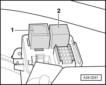
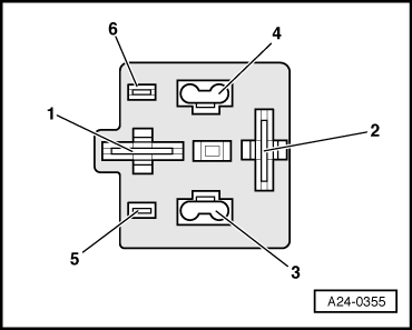
Testing secondary air pump relay -J299 and activation
 
G24-0023

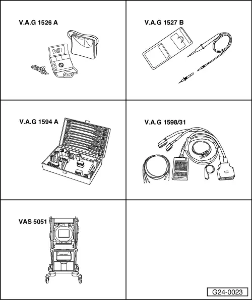
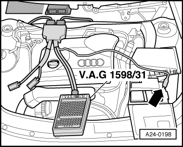
Special tools and workshop equipment required

  • ◆ V.A.G 1526 A
  • ◆ V.A.G 1527 B
  • ◆ V.A.G 1594 A
  • ◆ V.A.G 1598/31
  • ◆ VAS 5051 with VAS 5051/1
 
A01-0122

Test requirement:

  • ● Connect vehicle diagnosis, testing and information system VAS 5051, select "Vehicle self-diagnosis" and vehicle system "01 - Engine electronics".

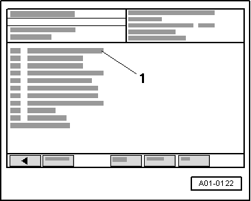
Test sequence

→ Display on VAS 5051:

  • ‒ Select diagnosis function "03 - Final control diagnosis" from the menu -1-
  • ‒ Activate secondary air pump relay -J299.
 
A24-0341
    • ‒ → Secondary air pump relay -1- should pick up and secondary air pump motor -V101 should run in intervals. (The relay is located under a cover on the left of the bulkhead).

A - If the relay does not pick up:

  • ‒ Test voltage supply of secondary air pump relay .
  • ‒ Test activation of secondary air pump relay => Page 26-55.

B - If the relay picks up but the secondary air pump motor does not run:

  • ‒ Test voltage supply of secondary air pump motor .
 
A24-0355

Testing voltage supply of secondary air pump relay

  • ‒ Switch off ignition.
  • ‒ Disconnect secondary air pump relay.
  • ‒ → Connect multimeter (voltage measurement range) as follows:

Relay carrier below cover on left side of bulkhead
Contact

Measure against

1

Engine earth

    • ‒ Specification: approx. battery voltage
 
A97-0116

If the specification is not obtained:

  • ‒ Carry out the following tests (marked with dots):
  • ● → Check fuse S130 (40 A) or S131 (50A) in main fuse box/battery.
  • ● Test for open circuit in wiring from battery + (terminal 30) via fuse S131 to secondary air pump relay -J299 (below cover on left side of bulkhead):

=> Current flow diagrams, Electrical fault finding and Fitting locations binder

 
A24-0355
  • ‒ → Connect multimeter (voltage measurement range) as follows:

Relay carrier below cover on left side of bulkhead
Contact

Measure against

3

Engine earth

  • ‒ Operate starter briefly.
    • ‒ Specification: approx. battery voltage
 
A97-0119

If the specification is not obtained:

  • ‒ Carry out the following tests (marked with dots):
  • ● → Check fuse S243 (fuse position 43 in fuse holder).
  • ● Test for open circuit in wiring from secondary air pump relay -J299 (below cover on left side of bulkhead) to fuel pump relay via fuse S243 (fuse position 43 in fuse holder):

=> Current flow diagrams, Electrical fault finding and Fitting locations binder

 
A24-0355

Testing activation of secondary air pump relay

  • ‒ Switch off ignition.
  • ‒ Disconnect secondary air pump relay.
  • ‒ → Connect voltage tester V.A.G 1527 B as follows:

Relay carrier below cover on left side of bulkhead
Contact

Measure against

4

Battery positive

 
A01-0122

→ Display on VAS 5051:

  • ‒ Select diagnosis function "03 - Final control diagnosis" from the menu -1-
  • ‒ Activate secondary air pump relay -J299.
    • ‒ The LED should flash.

 
A24-0198

If the LED does not flash:

  • ‒ Switch off ignition.
  • ‒ → Connect test box V.A.G 1598/31 to wiring harness connectors. The engine control unit itself does not need to be connected to the test box. Connect earth clamp on test box to earth -arrow-.

=> Motronic injection and ignition system; Repair group 24

 
A24-0355
  • ‒ → Test for open circuit and short to positive or earth in the following wiring connections:

Relay carrier below cover on left side of bulkhead
Contact

Test box V.A.G 1598/31
Socket

4

9

  • ‒ Rectify any open/short circuit as necessary.

If no fault is found:

  • ‒ Fit a new secondary air pump relay -J299.
 
A02-0063

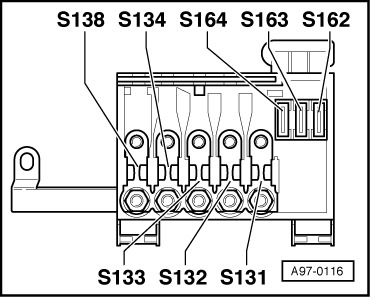
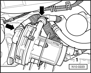
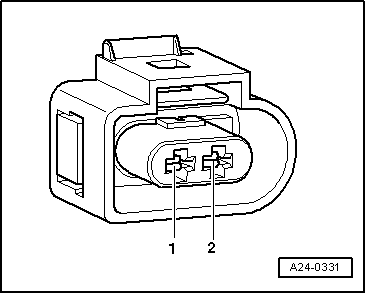
Testing voltage supply to secondary air pump motor

  • ‒ → Remove noise insulation centre panel -arrows-.

 
N10-0223
  • ‒ → Unplug connector -1- from secondary air pump motor -V101.
 
A24-0331
  • ‒ → Connect voltage tester V.A.G 1527 B between contacts 1 and 2.

 
A01-0122

→ Display on VAS 5051:

  • ‒ Select diagnosis function "03 - Final control diagnosis" from the menu -1-
  • ‒ Activate secondary air pump relay -J299.
    • ‒ The LED should flash.

If the LED does not flash:

  • ‒ Carry out the following tests (marked with dots):
  • ● Test for open circuit in wiring from connector on secondary air pump motor -V101 to secondary air pump relay -J299 (in relay carrier below cover on left side of bulkhead):

=> Current flow diagrams, Electrical fault finding and Fitting locations binder

  • ● Test for open circuit in wiring from contact 1 of connector to earth:

=> Current flow diagrams, Electrical fault finding and Fitting locations binder

If no fault is found:

  • ‒ Replace secondary air pump => Page 26-67.

Checking function of combination valve for secondary air system; checking for leaks > < Testing secondary air inlet valve -N112