audi Workshop Repair Guides

Audi Workshop Service and Repair Manuals

Checking control unit voltage supply > < Engine control unit
Motronic injection and ignition system (4-cyl.)
Engine control unit
Wiring and component check with test box V.A.G 1598/22

The following procedure applies to engine control units fitted with a protective metal casing.

Notes:

  • ◆ The instructions for performing the individual tests indicate whether or not the engine control unit itself also needs to be connected to the test box.
  • ◆ Always use adapter set V.A.G 1594A to connect test equipment (e.g. voltage tester V.A.G 1527B, hand-held multimeter V.A.G 1526A etc.).

Work sequence

  • ‒ Switch off ignition.
  • ‒ Unbolt windscreen wiper arms.
  • ‒ Remove plenum chamber cover and rest it against the windscreen.
 
A24-0540

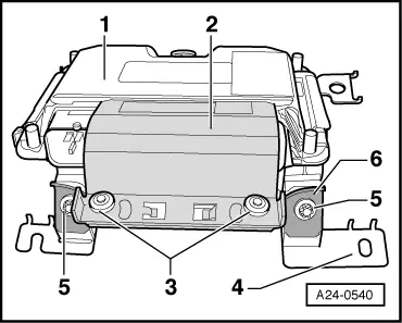
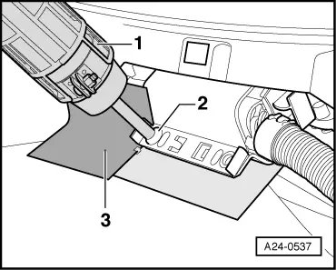
Note:

Item -1- in the illustration shows the engine control unit with protective metal casing.

 
A24-0540

→ As a deterrent against unauthorised access to the connectors on the engine control unit, the control unit -1- is bolted to a metal casing -4- by means of shear bolts -3- and a locking plate -2-.

The threads of the shear bolts are additionally coated with a thread-locking compound to make them more difficult to remove.

In order to unplug the connectors from the engine control unit (for instance when connecting the test box), the locking plate -2- must be separated from the protective casing. The required procedure is described below:

 
A24-0475

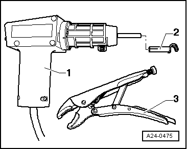
The following tools are required:

  • ◆ → Hot-air blower -1- (from wiring repair set VAS 1978)
  • ◆ A normal (commercially available) vice-grip wrench

Procedure:

Caution
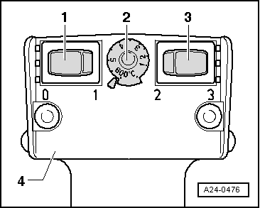
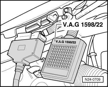
Keep exactly to the following procedure to avoid damage (burning) to the wiring, connectors, insulation or the control units. Follow the operating instructions supplied with the hot-air blower.
 
A24-0538

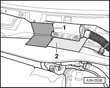
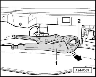
→ To avoid damage to wiring or connectors, use heat shields (Items -1- and -2-, consisting of metal plates).
This should protect the connector housing and wiring harness from overheating.

 
A24-0476
  • ‒ → Set controls on hot-air blower as shown in illustration:
    temperature control -2- to maximum heat and two-stage air delivery switch -3- to setting 3.

Note:

In the next step the blower is used to heat the shear bolt in the locking plate. This reduces the effect of the thread-locking compound so the bolts can then be removed more easily.

Warning
When the threads in the locking plate are heated up, this also heats the shear bolts and parts of the metal casing. Take care not to burn your hands. Also make sure that, as far as possible, you only apply heat to the threads and not to the adjacent parts. Cover these up if necessary.

 
A24-0537
  • ‒ → Apply nozzle -1- of hot-air blower to bolt -2- on locking plate.

Note:

Be particularly careful here because the control unit connectors are very close to this bolt.

  • ‒ Switch on the blower and apply heat to the thread for about 20 to 25 seconds.

 
A24-0539
  • ‒ → Apply vice-grip wrench -1- to bolt head -2- and unscrew shear bolt in direction indicated (arrows).
  • ‒ For added protection, the locking plate is positioned so that the wrench cannot be turned through one full turn.

Repeat the procedure for the second shear bolt. Be particularly careful here because the control unit connectors are very close to this bolt.

  • ‒ When the second bolt has been removed, you can take off the locking plate for the connectors.
  • ‒ Release catches and unplug control unit connectors.
 
N24-0709
  • ‒ → Connect test box V.A.G 1598/22 to wiring harness connectors.
  • ‒ Carry out test as described in the repair instructions.

Perform the following operations after reconnecting engine control unit:

Installation is performed in the reverse sequence. Install metal casing (with locking plate) on engine control unit. Use new shear bolts.

  • ‒ Interrogate fault memory and erase if necessary.

Checking control unit voltage supply > < Engine control unit