audi Workshop Repair Guides

Audi Workshop Service and Repair Manuals

Testing Hall sender -G163 > < Testing knock sensor control limit
Motronic injection and ignition system (4-cyl. turbo)
Testing ignition system
Testing knock sensors
 
G24-0020

Special tools and workshop equipment required

  • ◆ V.A.G 1526 A
  • ◆ V.A.G 1594 A
  • ◆ V.A.G 1598/31

Fitting location => Fitting locations overview, Page 24-5

Notes:

  • ◆ It is not possible to carry out an electrical test of the knock sensors themselves (-G61 and -G66).
  • ◆ Always use gold-plated contacts when repairing the knock sensor connectors.
  • ◆ To ensure that the knock sensors function properly it is important to keep exactly to the specified tightening torque of 20 Nm.
  • ◆ Check for corrosion in connection between knock sensor and wiring harness.

Testing knock sensors

  • ‒ Unplug the connector for the relevant knock sensor in the engine compartment.
 
A28-0029
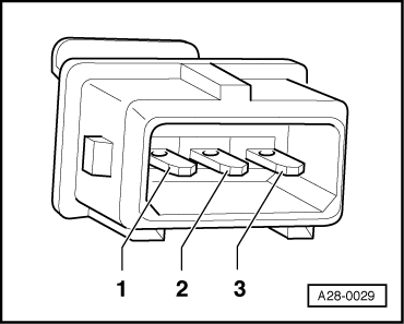
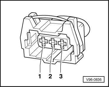
  • ‒ → Test for short circuits between all three contacts in the knock sensor connector (contacts 1+2, 1+3 and 2+3).
    • ‒ Specification: ∞ ω (no continuity) - there must be no connection between any of the contacts.
  • ‒ If there is a connection between the contacts, fit a new knock sensor.
  • ‒ If there is no short circuit, test wiring for knock sensors.

Testing wiring between knock sensors and engine control unit

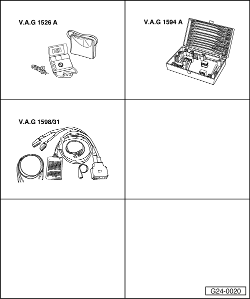
  • ‒ Connect test box V.A.G 1598/31 to wiring harness for engine control unit. Do not connect to the engine control unit itself.
    .
  • ‒ Test for open circuit and short to positive or earth in the following wiring connections:
 
V96-0836
  • ● → Knock sensor 1 -G61 (cylinders 1/2)

Connector for -G61
Contact

Test box V.A.G 1598/31
Socket

1 (signal)

106

2 (earth)

99

3 (screening)

108

  • ● Knock sensor 2 -G66 (cylinders 3/4)

Connector for -G66
Contact

Test box V.A.G 1598/31
Socket

1 (signal)

107

2 (earth)

99

3 (screening)

108

  • ‒ Rectify any open/short circuit as necessary.

Testing Hall sender -G163 > < Testing knock sensor control limit