A3 Mk1
|
|
|
 Note
Note
Note
|
|
|
|
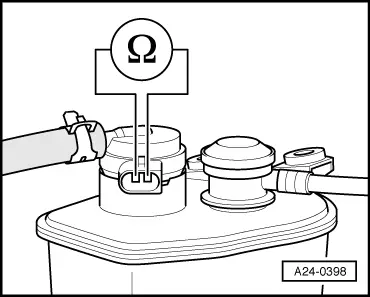
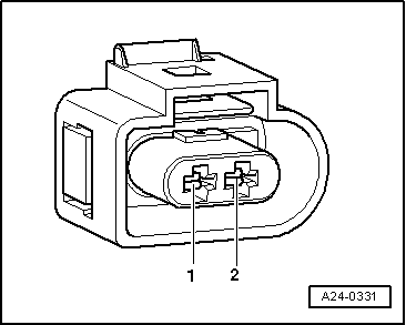
| Connector Contact | Measure to |
| 1 | Engine earth |
|
|
|
|
|
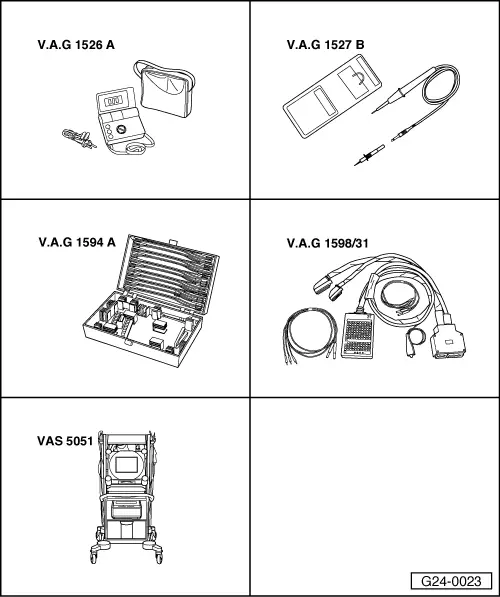
| Connector Contact | Test box -V.A.G 1598/31- Socket |
| 2 | 64 |
|

|
|
|
Note
Note
|
|
|
|
| Connector Contact | Measure to |
| 1 | Engine earth |
|
|
|
|
|
| Connector Contact | Test box -V.A.G 1598/31- Socket |
| 2 | 64 |
|