audi Workshop Repair Guides

Audi Workshop Service and Repair Manuals

Testing clutch pedal switch -F36 > < Testing coolant temperature sender -G62
TDI®injection and glow plug system (4-cyl. unit injector)
Testing control unit input values
Checking brake light switch -F and brake pedal switch -F47

Note:

For safety reasons, the signal from the accelerator position sender (potentiometer) instructing the engine control unit to increase the engine speed is suppressed whenever the brake is operated. The engine control unit therefore needs the brake light switch signal and also the brake pedal switch signal.

If the brake is operated while the accelerator is held down at a constant position, the engine is immediately governed down to idling speed. A defective switch can cause the engine to be throttled back when this is not desired.

 
A01-0139

Test sequence

  • ‒ Read data block, Display group 006
    => Page 01-86.

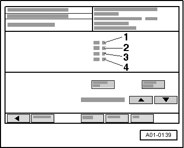
→ Display on VAS 5051:

  • ‒ Check display in display zone -2-.
    • ‒ Specification: 0 0 0
  • ‒ Slowly depress brake pedal.
    • ‒ Specification: 0 1 1
      The two display values should change from 0 to 1.
  • ‒ Allow brake pedal to return slowly to its normal position.
    • ‒ Specification: 0 0 0
      The two display values should change back from 1 to 0.
  • ‒ Press the ◂ button to exit from the function "08 - Read data block".
  • ‒ Select diagnosis function "06 - End output".
  • ‒ Switch off ignition.
 
A24-0205

If the display values do not appear as described:

Testing switches

  • ‒ Remove storage compartment (shelf) on driver's side.

=> General body repairs, Interior; Repair group 68; Storage compartments, covers; Removing driver's storage compartment

  • ‒ → Unplug connector from brake light switch / brake pedal switch -arrow-.
 
A24-0210
  • ‒ → Connect multimeter (resistance measurement range) between contacts 1 and 4.
    • ‒ Specification: ∞ ω (no continuity)
  • ‒ Depress the brake pedal.
    • ‒ Specification: approx. 0 ω
  • ‒ Connect multimeter (resistance measurement range) between contacts 2 and 3.
    • ‒ Specification: approx. 0 ω
  • ‒ Depress the brake pedal.
    • ‒ Specification: ∞ ω (no continuity)

If the specifications are not obtained:

  • ‒ Renew brake light switch / brake pedal switch.

If the specifications are obtained:

  • ‒ Check voltage supply.
 
A24-0200

Checking voltage supply

  • ‒ → Connect voltage tester V.A.G 1527 B as follows:

Connector
Contact

Measure against

1

Body earth

    • ‒ The LED should light up.

Connector
Contact

Measure against

2

Body earth

  • ‒ Switch on ignition.
    • ‒ The LED should light up.
  • ‒ Switch off ignition.

If the LED does not light up:

  • ‒ Test wiring for open circuits and rectify if necessary.

If the LED lights up:

Checking wiring connections

  • ‒ Connect test box V.A.G 1598/31 to wiring harness for engine control unit.Do notconnect to the engine control unit itself:
    • ‒ Connecting test box to engine control unit without protective housing=>Page 23-49.
    • ‒ Connecting test box to engine control unit with protective housing=>Page 23-51.
 
A24-0200
  • ‒ → Test for open circuit and short to positive or earth in the following wiring connections:

Connector
Contact

Test box V.A.G 1598/31
Socket

3

65

4

32

  • ‒ Rectify short circuit or open circuit if necessary.

If no fault is found:

  • ‒ Replace engine control unit
    • ‒ Removing and installing engine control unit without protective housing=>Page 23-57.
    • ‒ Removing and installing engine control unit with protective housing=>Page 23-60.

Testing clutch pedal switch -F36 > < Testing coolant temperature sender -G62