audi Workshop Repair Guides

Audi Workshop Service and Repair Manuals

Testing fuel temperature sender -G81 > < Testing clutch pedal switch -F36
TDI®injection and glow plug system (4-cyl. unit injector)
Testing control unit input values
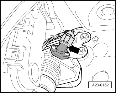
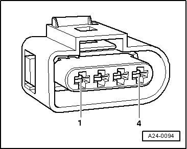
Checking intake manifold temperature sender -G72
 
A01-0139

Test sequence

  • ‒ Read data block, Display group 007, engine cold and not running=>Page01-131

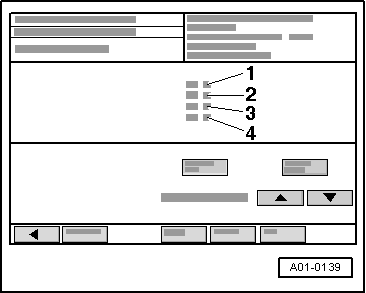
→ Display on VAS 5051:

  • ‒ Check readouts in display zones -1-, -3- and -4-.
    • ‒ Specification: All temperature values approx. the same
  • ‒ Press the ◂ button to exit from the function "08 - Read data block".
  • ‒ Select diagnosis function "06 - End output".
  • ‒ Switch off ignition.
 
A23-0152

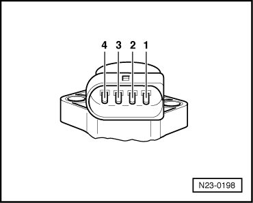
If an implausible value is displayed in display zone 3 (substitute value if fault occurs: 135.9 °C):

Testing internal resistance

  • ‒ Remove windscreen washer fluid reservoir.
  • ‒ → Unplug connector at intake manifold temperature sender -G72 (in charge air cooler) -arrow-.
 
N23-0198
  • ‒ → Connect multimeter between contacts 1 and 2 of sender (resistance measurement range).

 
N24-0157

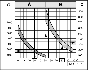
Scale A shows resistance values for temperature range 0...50 °C and scale B the values for temperature range 50...100 °C.

→ Examples:

  • ◆ 30 °C corresponds to a resistance from 1500...2000 ω
  • ◆ 80 °C corresponds to a resistance from 275...375 ω

If the specification is not obtained:

  • ‒ Renew intake manifold pressure sender with intake manifold temperature sender.

If the specification is obtained:

Checking wiring connections

  • ‒ Connect test box V.A.G 1598/31 to wiring harness for engine control unit.Do notconnect to the engine control unit itself:
    • ‒ Connecting test box to engine control unit without protective housing=>Page 23-49.
    • ‒ Connecting test box to engine control unit with protective housing=>Page 23-51.
 
A24-0094
  • ‒ → Test for open circuit and short to positive or earth in the following wiring connections:

Connector
Contact

Test box V.A.G 1598/31
Socket

1

52

2

73

  • ‒ Test all wires for short circuits with each other.
  • ‒ Rectify any open/short circuit as necessary.

If no fault is found:

  • ‒ Replace engine control unit
    • ‒ Removing and installing engine control unit without protective housing=>Page 23-57.
    • ‒ Removing and installing engine control unit with protective housing=>Page 23-60.

Testing fuel temperature sender -G81 > < Testing clutch pedal switch -F36