audi Workshop Repair Guides

Audi Workshop Service and Repair Manuals

Vane pump > < Adjusting power-assisted steering box
Running gear, Front-wheel drive and four-wheel drive
Servicing power steering
Removing and installing power-assisted steering box
 
G48-0019

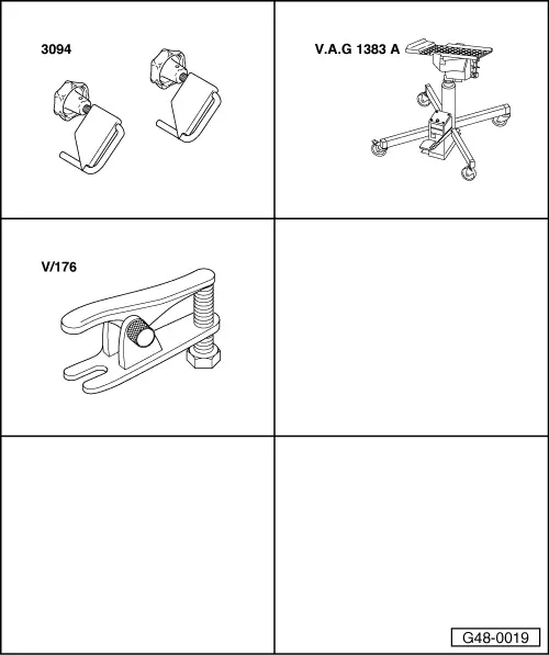
Special tools and workshop equipment required

  • ◆ Hose clamps 3094
  • ◆ Engine/gearbox lifter V.A.G 1383 A
  • ◆ Ball joint puller Matra V/176
  • ◆ Caliper gauge
 
A48-0239

Note:

Observe rules for cleanliness .

Attention:
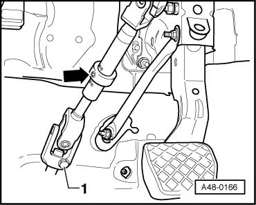
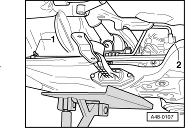
Steering box must be removed with front wheels in straight ahead position so as not to damage return spring with slip ring at steering column switch.
  • ‒ → With wheels in straight ahead position, secure steering wheel with adhesive tape to prevent inadvertent turning -arrows-.

 
A48-0104

Left-hand drive vehicles:

  • ‒ → Unscrew plastic nuts -1- and take out cover -A-.
 
A48-0164

Right-hand drive vehicles:

  • ‒ → Remove footrest -arrows-.

 
A48-0166

All models:

  • ‒ → Screw out bolt -1-.
  • ‒ On vehicles with clamping ring -arrow-, slacken off hexagon socket-head bolt until mesh section can be compressed.
  • ‒ Detach universal joint from steering box.
 
N48-0298
  • ‒ → Pinch off hose from reservoir with hose clamp 3094.

 
N48-0309
  • ‒ → Pinch off hose at vane pump with hose clamp 3094.
 
A48-0110
  • ‒ → Detach noise insulation -arrows-.

 
A10-0458
  • ‒ → On vehicles with automatic headlight range control, unscrew bracket for headlight range control unit at top left of wheel housing -arrows-.
 
A48-0105
  • ‒ Unscrew nut from track rod end.

Notes:

  • ◆ Leave nut screwed several turns onto track rod end to protect thread.
  • ◆ Fig. shows Audi A3 vehicle.
  • ‒ → Use puller Matra V/176 -Item 1- to press track rod off steering arm.

 
A48-0111

Left-hand drive vehicles:

  • ‒ Place drip tray in position.
  • ‒ → Unscrew expansion hose -2- from steering box and seal off with a plastic bag and adhesive tape.
  • ‒ Seal tapped hole at steering box (using plastic plug for example).
  • ‒ Return pipe -1- can be unscrewed after lowering subframe.
 
A48-0167

Right-hand drive vehicles:

  • ‒ Place drip tray in position.
  • ‒ → Unscrew expansion hose -arrow- from steering box and seal off with a plastic bag and adhesive tape.

 
A48-0168
  • ‒ → Unscrew return pipe -arrow- from steering box and seal off with a plastic bag and adhesive tape.
  • ‒ Seal tapped hole at steering box (using plastic plug for example).
 
A10-0928

All models:

  • ‒ → Unscrew pendulum support at gearbox -arrows B-.

 
A34-0238
  • ‒ → If fitted, disengage rubber mount at front exhaust pipe -arrow-.
  • ‒ Slacken off bolts -2- for steering box by several turns.
 
A40-0305
  • ‒ → Prise steering box off subframe (dowel sleeve) -arrow-.
  • ‒ Unscrew holder for power steering pressure pipe on left of subframe.
  • ‒ Position engine/gearbox lifter V.A.G 1383 A with universal mount V.A.G 1359/2 and wooden block beneath subframe.

 
A34-0238
  • ‒ → Screw out bolts -1- and -3- for subframe.
  • ‒ Carefully lower subframe slightly.

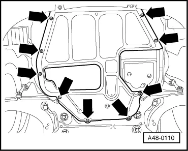
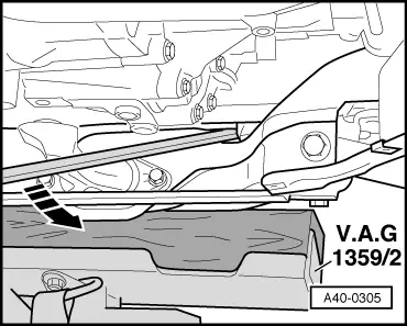
Note:

When lowering, pay attention to side noise insulation and holder for hydraulic pipes on left side.

 
A48-0107

Left-hand drive vehicles:

  • ‒ → Unscrew return pipe from clamp -1- and unscrew rotary slide valve housing -2-.

All models:

  • ‒ Screw out steering box bolts and take out steering box to rear.

 
N48-0284

Installing

Note:

Use new sealing rings for hose/pipe connections.

Left-hand drive vehicles:

    • ‒ Position steering box on subframe and fit steering box bolts.
    • ‒ → Threaded sleeve -1- must be positioned in hole in subframe
    • ‒ Rubber insert on opposite side must be positioned on corresponding projection on subframe
 
A48-0169

Right-hand drive vehicles:

    • ‒ Position steering box on subframe and fit steering box bolts.
    • ‒ → Threaded sleeve -arrow- must be positioned in hole in subframe
    • ‒ Rubber insert on opposite side must be positioned on corresponding projection on subframe
 
A48-0137

All models:

  • ‒ → Dimension -a- must be checked to ensure that steering box is in centre position.
  • ‒ Take measurement on left of steering box for LHD/on right of steering box for RHD.
    • ‒ Audi A3: Dimension a = 30.5 mm
    • ‒ Audi S3: Dimension a = 33.5 mm
  • ‒ Adjust by turning steering box pinion.

 
A48-0138

Left-hand drive vehicles:

  • ‒ → Screw return pipe to clamp at steering box.

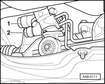
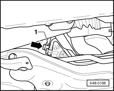
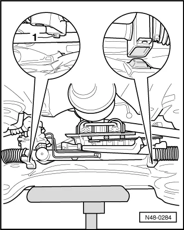
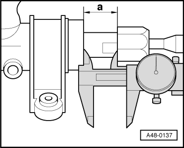
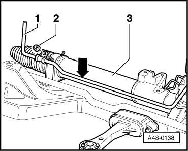
Note:

On front-wheel drive vehicles, there must be a gap of 10 mm between return pipe -1- and steering box -3-.

  • ‒ Screw return pipe with new sealing rings to rotary slide valve housing.
 
A48-0168

Right-hand drive vehicles:

  • ‒ → Screw return pipe with new sealing rings to rotary slide valve housing.

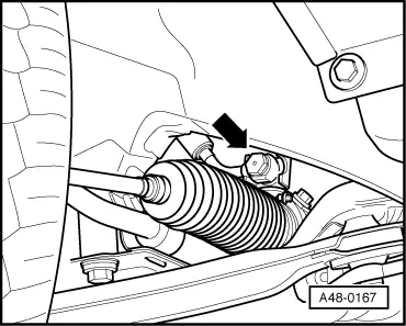
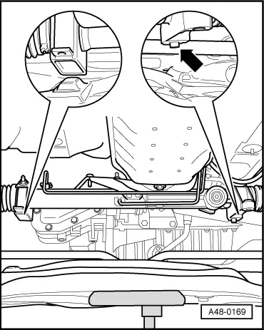
Note:

Make sure return pipe rests on locating pin -1-.

All models:

Note:

When securing pipes, make sure they cannot catch or become abraded.

  • ‒ Check correct positioning of sealing collar at steering box pinion.
  • ‒ Raise subframe and, in doing so, guide steering box pinion into opening in floor of vehicle.

Perform further installation in reverse order, paying attention to the following:

  • ‒ Install subframe .
  • ‒ Insert track rods in steering arm. If joint pin rotates on tightening, provide support with Allen key (6 mm) or Torx socket wrench (T40).
  • ‒ Do not attach universal joint of steering column to steering box pinion until vehicle is standing on ground and wheels are set to straight ahead position.
 
A48-0166
  • ‒ → Tighten bolt -1-.
  • ‒ Tighten hexagon socket-head bolt on vehicles with clamping ring
    -arrow-.
  • ‒ Top up hydraulic fluid - bleed steering system.

=> Maintenance

Tightening torques

Component

Nm

Universal joint to steering pinion

20 + 90° 1)2)

Clamping ring to steering column

17

Ball joint to wheel bearing housing

45 2)

    1)    90°corresponds to quarter turn

    2)    Replace nuts/bolts

Perform wheel alignment after installation.

Vane pump > < Adjusting power-assisted steering box