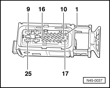
audi Workshop Repair Guides

Audi Workshop Service and Repair Manuals

Test table > < Electrical check of ABS, ABS/EDL and ABS/EDL/TCS ITT Mark 20 without ESP
Connecting adapterV.A.G 1598/21 (test box) to ABS with EDL control unitJ104
Connecting adapter -V.A.G 1598/21- (test box) to ABS with EDL control unit -J104-
   
–  Switch off ignition.
–  If fitted, remove cover at front left of engine compartment -arrows-.
  A10-1254
–  If fitted, disconnect air intake hose for secondary air pump -1- from air cleaner housing.
–  Detach air intake hose -2- at air mass meter.
–  Unplug electrical connector at air mass meter -3-.
–  Unscrew bolts -4- and -5-.
–  Take out air cleaner housing.
  A10-0443
–  Release 25-pin connector at ABS with EDL control unit -J104--arrow 1- and detach -arrow 2-.
  N45-0121
–  Connect adapter -V.A.G 1598/21- (test box) -item 1- to unplugged 25-pin connector -2- of ABS with EDL control unit -J104-.
  Caution
To prevent damage to the electronic components, select the respective measuring range and note the test requirements prior to connecting test leads.
–  Perform all steps listed for “fault rectification if reading does not match specification”.
–  Only carry out the test steps recommended in the fault table (to trace a specific fault).
–  After performing electrical check, plug 25-pin connector onto pins of ABS with EDL control unit -J104- and secure connector.
  Note
t  Use hand-held multimeter -V.A.G 1526 B- with test leads from -V.A.G 1594 C- or vehicle diagnostic, testing and information system -VAS 5051 A- with test leads -VAS 5051 A/7- for the electrical check.
t  The socket designations of the adapter -V.A.G 1598/21- (test box) are identical to the contact designations of the ABS with EDL control unit -J104- in the current flow diagram.
t  Incorrect test procedures can cause system damage. Do not make bridging connections between any contacts other than those listed in the test table.
t  The specified values are valid for an ambient temperature between 0 ... 40 °C.
t  If measured values differ from specifications, locate fault according to current flow diagram.
t  If the measured values only differ slightly from the specifications, clean the sockets and plugs of the testers and test leads (with contact spray -G 000 700 04-) and repeat the check.
t  Before renewing components, check wiring and connections. Repeat resistance check on the component, particularly where specifications call for a resistance of less than 10Ω.
  N01-0018
25-pin connector of ABS with EDL control unit -J104- / sockets on adapter -V.A.G 1598/21- (test box)
  N45-0037
1 -Speed sensor, front left -G47-“+”15 -
t  Vehicles with TCS: Traction control system switch -E132- and traction control system warning lamp -K86-
2 -Speed sensor, front left -G47-“–” 
t  Vehicles with four-wheel drive: Longitudinal acceleration sender -G251-
3 -Coding bridge to contact 1416 -ABS warning lamp -K47-
4 -Power supply, terminal 75/75a in dash panel wiring harness (via fuse)17 -Vehicles with four-wheel drive: Longitudinal acceleration sender -G251-
5 -Speed sensor, rear left -G46-“+”18 -Brake light switch -F-
6 -Speed sensor, rear left -G46-“–”19 -Speed sensor, front right -G45-“+”
7 -Diagnosis K-wire20 -Speed sensor, front right -G45-“–”
8 -Earth point in wiring harness of engine compartment21 -Vehicles with navigation system: navigation system with CD drive control unit -J401-
9 -Battery “+” via fuse22 -Speed sensor, rear right -G44-“–”
10 -From model year 1998 onwards: CAN bus Low23 -Speed sensor, rear right -G44-“+”
11 -From model year 1998 onwards: CAN bus High24 -Earth terminal 31
12 -Vehicles with navigation system: navigation system with CD drive control unit -J401-25 -Battery “+” (ABS hydraulic pump -V64- via fuse)
13 -Vehicles with four-wheel drive: Longitudinal acceleration sender -G251-  
14 -Coding bridge to contact 3  


Test table > < Electrical check of ABS, ABS/EDL and ABS/EDL/TCS ITT Mark 20 without ESP