audi Workshop Repair Guides

Audi Workshop Service and Repair Manuals

ABS, ABS/EDL and ABS/EDL/TCS ITT Mark 20 without ESP > < Two control units communicating via a "Two-line bus system”.
Three or more control units communicating via a “Two-line bus system”.
   
Example 1:
The faults stored in the fault memories indicate that the control unit -1- has no connection to control units -2- and -3-.
  A01-0027
Control unitFaults stored in fault memory
-1-
t  No message from control unit -2-
t  No message from control unit -3-
-2-
t  No message from control unit -1-
-3-
t  No message from control unit -1-

–  Switch off ignition.
–  Unplug electrical connectors on control units linked by data bus wires and check bus wires for open circuit → Current flow diagrams, Electrical fault finding and Fitting locations.
   
Example 2:
The faults stored in the fault memories indicate that the control unit -2- does not communicate with control units -1- and -3-.
  A01-0028
Control unitFaults stored in fault memory
-1-
t  No message from control unit -2-
-2-
t  No message from control unit -1-
t  No message from control unit -3-
-3-
t  No message from control unit -2-

–  Switch off ignition.
–  Unplug electrical connectors on control units linked by data bus wires and check bus wires for open circuit → Current flow diagrams, Electrical fault finding and Fitting locations.
   
Example 3:
The faults stored in the fault memories indicate that none of the control units can transmit or receive.
  A01-0029
Control unitFaults stored in fault memory
-1-
t  Control unit defective
-2-
t  Control unit defective
-3-
t  Control unit defective

–  Switch off ignition.
–  Unplug electrical connectors on control units linked by data bus wires and check bus wires for short circuit → Current flow diagrams, Electrical fault finding and Fitting locations.
   
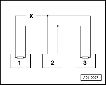
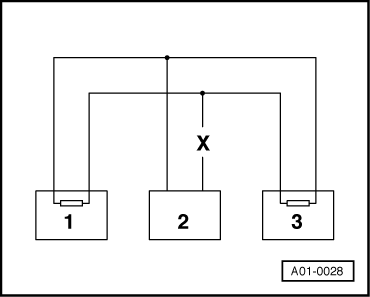
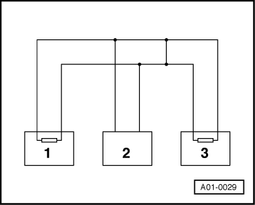
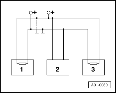
–  Check the bus wires for short to positive and short to earth.
–  If the cause of the fault “Control unit defective” cannot be found in the data bus wires, check whether one of the control units is responsible for causing the fault.
l  Electrical connectors on all control unit that communicate via the CAN data bus are unplugged.
l  Ignition switched off
–  Connect one of the control units.
–  Connect vehicle diagnostic, testing and information system -VAS 5051 A- → Chapter.
–  Switch on ignition and select the relevant vehicle system.
–  Interrogate and erase the fault memory of the control unit which has been just connected.
–  Terminate function “05 - Erasing fault memory” by touching key.
–  Conclude the transfer of data with the function “06 - End output”.
–  Switch the ignition off and then on again.
–  Leave the ignition switched on for 10 seconds. Then interrogate the fault memory of the control unit that has just been connected.
If the fault “control unit defective” is indicated:
–  Renew the control unit which has just been connected.
If the fault “control unit defective” is not indicated:
–  Connect the next control unit and repeat the procedure.
  A01-0030

ABS, ABS/EDL and ABS/EDL/TCS ITT Mark 20 without ESP > < Two control units communicating via a "Two-line bus system”.