audi Workshop Repair Guides

Audi Workshop Service and Repair Manuals

Exploded view - gearbox housing > < Assembly sequence - gearbox without circlip for input shaft sealing cap
Assembly sequence - gearbox with circlip for input shaft sealing cap
Removing and installing gearbox housing, selector mechanism, input shaft, output shafts (pinion shafts), differential, bevel box and selector rods
  Note
   
Sealing cap for input shaft with circlip -A-
  N34-11100
Special tools and workshop equipment required
t  Support plate -VW 309-
t  Support clamp -VW 313-
t  Gearbox support -VW 353-
t  Installing sleeve -VW 455-
t  Multi-purpose tool -VW 771-
t  -1- Kukko 21/01 internal puller
t  -3- Kukko 17/0 splitter
t  -4- Kukko 22/1 counter-support

   
t  Support bridge -30 - 211 A-
t  Thrust piece -T10143-
t  Drift -T10169-
t  Thrust piece -T40008-
t  Torque wrench -V.A.G 1331-
t  Hot air blower -V.A.G 1416-

   
t  Oil seal extractor lever -VW 681-
  W00-0154
t  Used oil collection and extraction unit -V.A.G 1782-
  W00-10211
t  Socket and extended bit -T10107 A-
Removing
l  Gearbox removed and mounted on assembly stand → Chapter.
–  Turn gearbox on assembly stand so that oil drain plug faces downwards.
–  Place used oil collection and extraction unit -V.A.G 1782- below gearbox.
–  Drain off gear oil.
  W00-10595
–  Unscrew bolt for flange shaft (right-side) using socket and extended bit -T10107 A-.
–  Remove all 4 bolts -arrows- securing bevel box to gearbox (illustration only shows 3 bolts).
–  Carefully push bevel box away from gearbox, making sure it does not fall down.
  A34-10040
–  Remove clutch slave cylinder with release bearing -arrows-.
  N34-0995
–  Make sure that the selector shaft is not locked in position by the angled rod -arrow- when carrying out the following steps.
–  Put selector shaft in neutral position.
–  Remove locking bolt -2-.
–  Remove bolts -3-.
–  Remove reversing light switch -F4--1-.
–  Pull selector shaft -4- out of gearbox housing.
  N34-10024
–  Remove bolt securing flange shaft (left-side). To do so, screw two bolts into flange and counterhold flange shaft with suitable lever.
  A39-0360
Gearbox for vehicles with start/stop system:
–  Remove gearbox neutral position sender -G701--arrow-.
  N34-11292
Continued for all gearboxes:
–  Remove bolts -B- securing gearbox housing from inside clutch housing.
  Note
One of the bolts -arrow- is outside the joint flange.
  N34-0997
–  Lock input shaft by fitting installing sleeve -VW 455- over input shaft and against clutch housing.
–  Tighten splitter-A-, e.g. -Kukko 17/0- behind splines on input shaft.
l  The rear side of the splitter must be in contact with installing sleeve (zero play).
  N34-10025
–  Remove circlip -A- for input shaft sealing cap.
  N34-11100
–  Pierce rubber in centre of sealing cap -C- with a screwdriver.
–  Pull sealing cap out of gearbox housing.
A - Counter-support, e.g. -Kukko 22/1-
B - Internal puller 8 ... 12 mm, e.g. -Kukko 21/01-
  N34-10026
Detach circlip -C- from input shaft grooved ball bearing as follows:
–  Hold one end of circlip with screwdriver-A-.
–  Lever other end of circlip out of slot in ball bearing -arrow- with 2nd screwdriver -B-.
–  Lever circlip out further by repositioning screwdriver-B-.
  N34-10027
–  Remove gearbox housing/clutch housing securing bolts -A-.
  N34-0923
–  Screw adapter VW 771/40 into threaded hole in gearbox housing.
–  Using hot air blower -V.A.G 1416-, heat area around seat of input shaft ball bearing in gearbox housing for approx. 10 minutes to approx. 100°C.
–  Using multi-purpose tool VW 771/1, pull gearbox housing off clutch housing -arrow-.
  Note
If necessary, carefully apply a lever to the protruding flanges on alternate sides of the gearbox housing, taking care not to damage the sealing surfaces.
  N34-10028
–  Remove splitter-A- and installing sleeve VW 455 from input shaft.
  Note
  N34-10025
A second mechanic is required for removing the shafts from the clutch housing.
–  Lift up differential -1- with your left hand.
–  With your right hand, lift 1st - 4th gear output shaft together with selector rods -2--arrow A-.
–  At the same time, the second mechanic must lift the input shaft, reverse shaft and 5th/6th gear output shaft -3- out of the clutch housing together with the selector rods -arrow B-.
  Note
If required, the differential can be put back in the clutch housing after lifting the shafts.
–  Remove oil seal for input shaft using oil seal extractor lever -VW 681-.
  Note
Always renew grooved ball bearing on input shaft → Item.
Installing
l  A new grooved ball bearing has been pressed onto the input shaft → Item.
  N34-10029
–  Insert input shaft -1-, output shaft for 5th and 6th gear -2- together with selector rod -3-, selector fork -4- and reverse shaft -5-.
  N34-10030
Up to gearbox manufacturing date 24 05 9:
l  Bearing for reverse gear selector fork:
–  Fit reverse gear selector fork -1- on shaft -2- behind selector rod for 5th/6th gear -3-.
  N34-11437
From gearbox manufacturing date 25 05 9 onwards
l  Bearing for reverse gear selector fork:
–  Fit reverse gear selector fork -1- on selector rod with selector fork for 5th/6th gear -2-.
  N34-11438
Continued for all gearboxes:
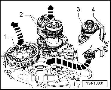
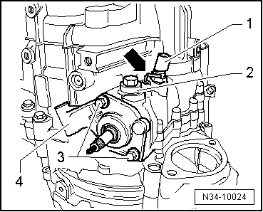
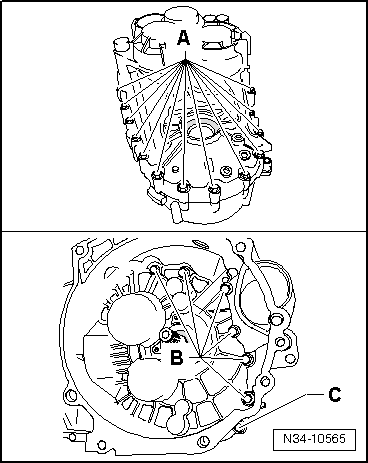
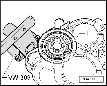
–  Install differential -1-.
  Note
A second mechanic is required for installing the shafts in the clutch housing.
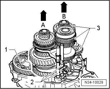
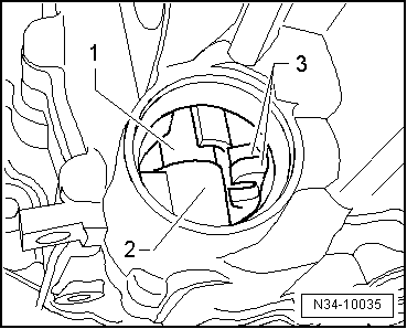
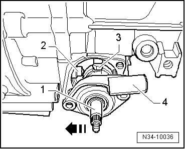
–  Take 1st - 4th gear output shaft -3- with selector rods -4- in your right hand as illustrated.
–  Lift differential slightly with your left hand.
–  At the same time, have the second mechanic lift the input shaft and output shaft for 5th, 6th and reverse gear -2- slightly, together with the reverse shaft.
–  Now insert 1st - 4th gear output shaft in direction of -arrow-.
l  
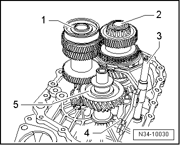
The teeth of the input shaft, output shafts and final drive gear/differential must mesh.
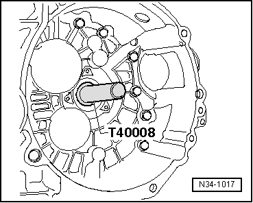
–  Now, together with second mechanic, locate shafts and differential in their bearing seats.
  N34-10031
–  Secure support bridge -30 - 211 A- for input shaft to clutch housing.
  Note
Illustration shows clutch housing turned through 180° for clarity.
–  Screw in bolt -A- until input shaft lifts slightly.
  N34-10032
l  Grooved ball bearing for input shaft will fit into gearbox housing in one position only.
The grooved ball bearing and the bearing mounting are flattened on one side.
l  If the sides are flattened -A- and -B-, a spacer must not be fitted above or below the grooved ball bearing → Chapter.
l  Flattened sides -A- on grooved ball bearing and bearing mounting -B- in gearbox housing must be aligned.
–  Mark flattened sides with paint.
–  Copy markings onto top area of grooved ball bearing and top area of bearing mounting on gearbox housing (⇒ next illustration).
–  Using hot air blower -V.A.G 1416-, heat area around seat of input shaft ball bearing in gearbox housing for approx. 10 minutes to approx. 100°C.
  Note
t  Heating is necessary to ensure that grooved ball bearing is not damaged when installing gearbox housing.
  N34-11101
t  Align marking -A- on grooved ball bearing with marking -B- on gearbox housing and fit gearbox housing.
–  Apply sealing paste -AMV 188 200 03- evenly to sealing surface of clutch housing.
  N34-11102
–  Fit gearbox housing and tighten new bolts -A-, -B- and -C- to specified torque.
Allocation of bolts:
A - Bolt with captive washer
B - Bolt without washer
C - Bolt with captive washer
  N34-10565
–  Install circlip -1- for input shaft grooved ball bearing.
–  Remove support bridge -30 - 211 A- for input shaft.
–  If stop sleeve for selector shaft has been removed, drive it in now → Fig. (drive in until tool reaches stop).
  N34-10033
–  Turn gearbox on assembly stand so that opening for selector shaft faces up.
–  Insert selector shaft -1- into bottom mounting -2- and into selector forks -3-.
  Note
The sealing cap is removed to give a better illustration.
  N34-10035
–  Now push selector shaft -1- against stop sleeve -2- in direction of -arrow- and run selector finger -3- down through selector forks and onto stop.
l  Selector mechanism cover -4- should be parallel to joint surface on gearbox housing.
l  Selector shaft should move up and down easily (gate selector movement).
  Note
If the selector mechanism cover is not parallel with the joint surface, the selector shaft is not seated in its bottom mounting.
  N34-10036
–  Tighten bolts -3- for selector mechanism cover -4-.
–  Screw in locking bolt -2-; angled rod -arrow- must be released.
–  Install reversing light switch -F4--1-.
  N34-10024
Gearbox for vehicles with start/stop system:
–  Install gearbox neutral position sender -G701--arrow- and tighten bolt → Item.
Continued for all gearboxes:
–  Install flange shaft (left-side) → Chapter.
  N34-11292
–  Drive in input shaft oil seal until flush.
–  Install clutch slave cylinder with release bearing → Chapter.
–  Select all gears.
  N34-1017
–  Drive sealing cap into gearbox housing onto stop.
  N34-11105
–  Secure sealing cap with circlip -A-.
Attach bevel box to gearbox as follows:
  Caution
The oil seal between the bevel box and the gearbox can be damaged.
Turn flange shaft while fitting bevel box with flange shaft (right-side) onto gearbox.
–  On manual gearbox, grease splines on differential with grease for clutch plate splines -G 000 100-.
–  Push bevel box fully onto gearbox, ensuring that splines of bevel box input shaft and differential are centred when brought together.
–  Also align the teeth of the flange shaft (right-side) and the differential pinion; if necessary turn the flange shaft.
–  If the teeth are correctly positioned and the components are located centrally, the bevel box will slide against the gearbox onto the stop.
  Note
Do not use the securing bolts to pull the bevel box onto the gearbox. This could cause the bevel box to tilt and the securing eyes could break off.
  N34-11100
–  Tighten all 4 bolts -arrows- securing bevel box to gearbox (illustration only shows 3 bolts). Tightening torques → Item
–  Install flange shaft (right-side) → Chapter.
  A34-10040

Exploded view - gearbox housing > < Assembly sequence - gearbox without circlip for input shaft sealing cap