
A3 Mk2
 Note
Note |
|
|

| Special tools and workshop equipment required |
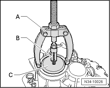
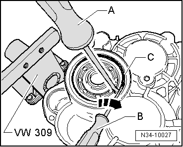
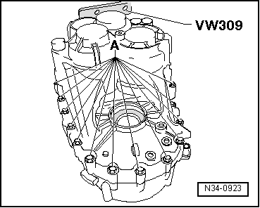
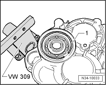
| t | Support plate -VW 309- |
| t | Support clamp -VW 313- |
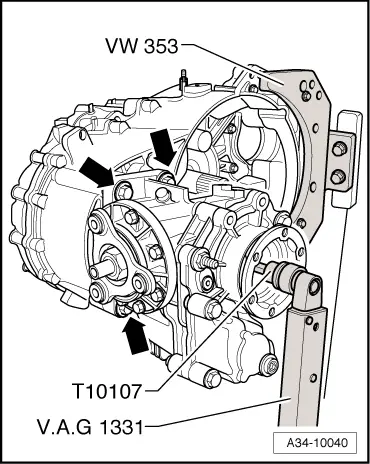
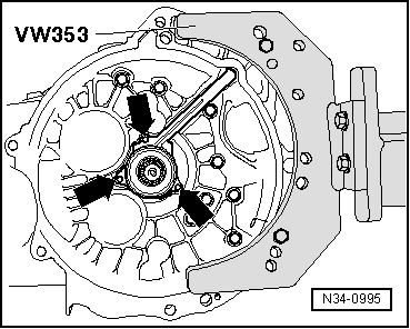
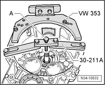
| t | Gearbox support -VW 353- |
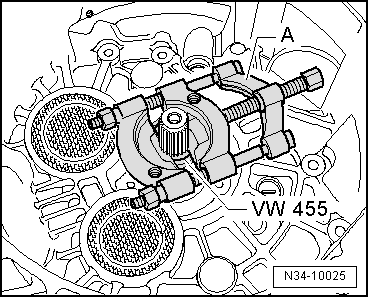
| t | Installing sleeve -VW 455- |
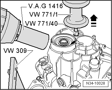
| t | Multi-purpose tool -VW 771- |
| t | -1- Kukko 21/01 internal puller |
| t | -3- Kukko 17/0 splitter |
| t | -4- Kukko 22/1 counter-support |

| t | Support bridge -30 - 211 A- |
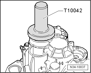
| t | Thrust piece -T10042- |
| t | Drift -T10169- |
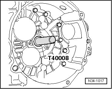
| t | Thrust piece -T40008- |
| t | Torque wrench -V.A.G 1331- |
| t | Hot air blower -V.A.G 1416- |
|
|
|
|
|
|
|
|
|
|
|
|
|
|
|
|
Note
|
|
|
|
|
|
|
|
|
|
|
|
Note
|
|
|
|
Note |
|
Note
Note
|
|
|
|
Note
|
|
Note
Note |
|
|
|
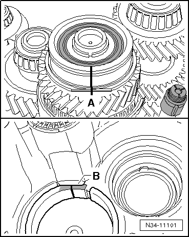
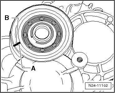
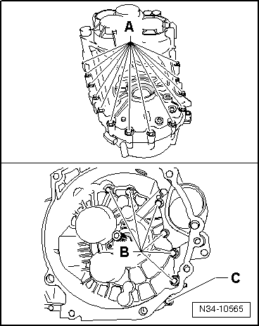
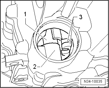
| Grooved ball bearing for input shaft and gearbox housing | ||
| Without flattened sides on grooved ball bearing -A- and bearing mounting -B- → Anchor | ||
| With flattened sides on grooved ball bearing -A- and bearing mounting -B- → Fig. |
|
| Top spacer | Outside diameter | 78.6 mm |
| Bottom spacer | Outside diameter | 85 mm |
|
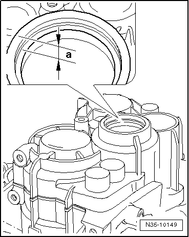
|
| Area above grooved ball bearing | Dimension “a” | Top spacer |
| Up to gearbox manufacturing date 09 04 6 | 10 mm | No |
| From gearbox manufacturing date 10 04 6 onwards | 10.7 mm | Yes |
|
|
| Area below bearing seat | Bottom spacer | |
| Up to gearbox manufacturing date 09 04 6 | Not modified | No |
| From gearbox manufacturing date 10 04 6 onwards | Slightly deeper | Yes |
|
|
|
|
Note
|
|
|
|
|
|
Note
|
|
Note
|
|
|
|
|
|
Note
|
|
 Caution
|
|