audi Workshop Repair Guides

Audi Workshop Service and Repair Manuals

Electrical checks at connector to auxiliary heater components > < Test step "3”
Signal from auxiliary heating radio controlled receiverR64
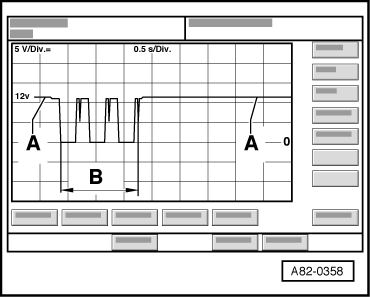
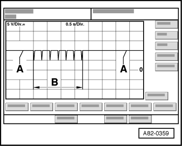
Signal from auxiliary heating radio controlled receiver -R64-
  Note
t  Pay attention to correct setting on oscilloscope to ensure that image shown in the two illustrations is displayed (operating mode “Auto”, voltage “DC”,trigger mode “negative edge” etc.).
t  To ensure proper oscilloscope response, approx. 4 V is to be set as the value for the trailing pulse (negative edge).
   
ON signal
-A- DC voltage signal, no signal being received (none of the auxiliary heater remote control buttons pressed)
-B- ON signal from auxiliary heater remote control being received (auxiliary heater remote control ON button is being or has been pressed)
  A82-0358
OFF signal
-A- DC voltage signal, no signal being received (none of the auxiliary heater remote control buttons pressed)
-B- OFF signal from auxiliary heater remote control being received (auxiliary heater remote control OFF button is being or has been pressed)
  A82-0359

Electrical checks at connector to auxiliary heater components > < Test step "3”