
A4 Cabriolet Mk2
| Removing gearbox - vehicles with 8-cyl. FSI engine (Audi RS 4) |
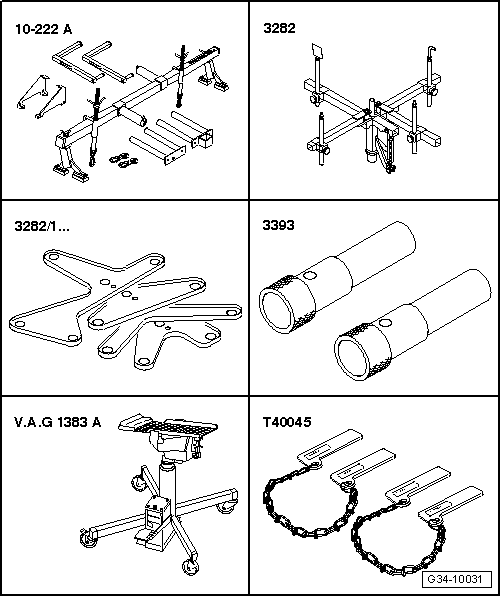
| Special tools and workshop equipment required |
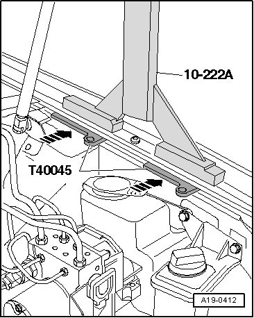
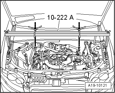
| t | Support bracket -10-222 A- |
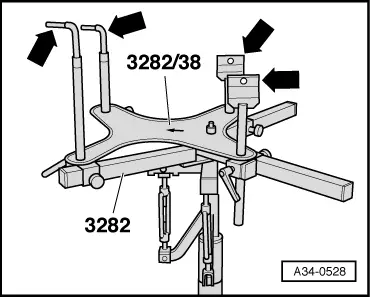
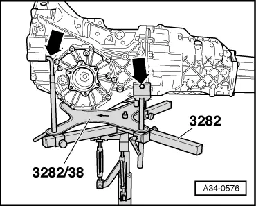
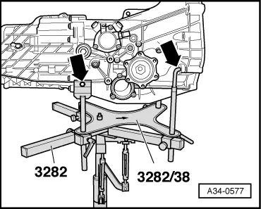
| t | Gearbox support -3282- |
| t | Adjustment plate -3282/38- |
| t | Locating pins -3393- |
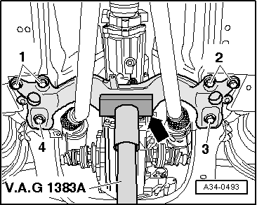
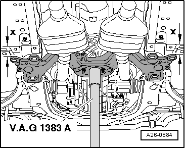
| t | Engine and gearbox jack -V.A.G 1383 A- |
| t | Wing compensation plates -T40045- |
| t | Drill Ø 10.2 mm |
| t | Bolt M10x20 (2x) |
| t | Copper grease -Z 381 351 TE- |
| t | Grease for clutch plate splines -G 000 100- |
 Note
Note
|
|
|
 Caution
|
|
|
|
|
|
|
|
|
|
|
|
Note
|
|
|
|
|
|
|
|
Note |
|
 WARNING
|
|
|
|
|
|
Note
|
|
Note
|
|
|
|
|
|
|
|
|
|
|
|
|
|
|
|
|
|
|
|
|
|
|
|
|
|
|
|
|
|
|
|
Note
|
|
|
|
Note
|
|
Note
|
|
|
|