audi Workshop Repair Guides

Audi Workshop Service and Repair Manuals

Dismantling and assembling shift mechanism in gearbox > < Removing and installing input shaft, pinion shaft, selector rods and gearbox cover
5-Speed Manual Gearbox 012/01W Front-wheel Drive
Dismantling and assembling gearbox
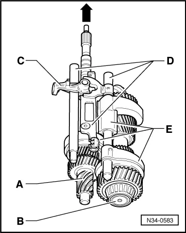
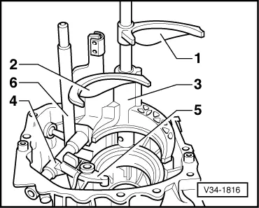
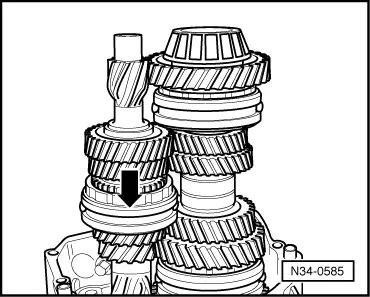
Removing and installing input shaft ball bearing, multi-function sender, input shaft, pinion shaft, selector rods and gearbox cover

Notes:

  • ◆ It is not necessary to remove the differential to remove the above-mentioned components.
  • ◆ Removal is only necessary when adjustments have to be carried out => adjustment overview, Page 39-39.

Special tools, testers and auxiliary equipment required

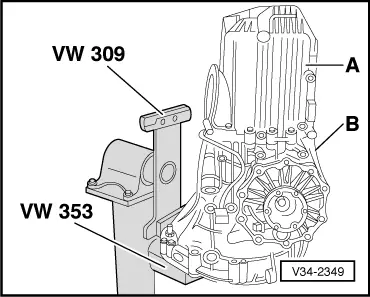
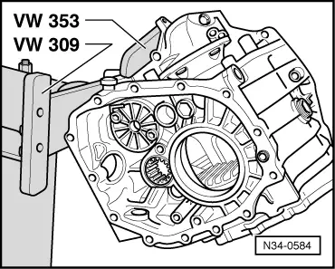
  • ◆ Holding plate VW 309
  • ◆ Gearbox support VW 353
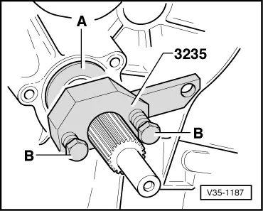
  • ◆ Pressing-in tool 3235
  • ◆ Drip tray V.A.G 1306
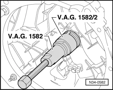
  • ◆ Taper roller bearing extractor V.A.G 1582
  • ◆ Clamping piece V.A.G 1582/2
  • ◆ Sealant AMV 188 001 02

Removing

  • ‒ Place drip tray V.A.G 1306 underneath the gearbox.
  • ‒ Drain gear oil.
  • ‒ Secure gearbox to repair stand .
 
V30-0375
  • ‒ → Detach clutch release lever -A- with release bearing.

Notes:

  • ◆ Before pulling off guide sleeve, cover input shaft splines with a shrink-fit hose to protect oil seal.
  • ◆ Removing oil seal from guide sleeve => Page 30-29.
  • ‒ Unscrew guide sleeve -B-.
  • ‒ Remove dished washer -C-.
  • ‒ Remove circlip -D- in front of input shaft ball bearing.
  • ‒ If the ball bearing, input shaft or gearbox housing is not to be replaced, note the thickness of the circlip.
 
N34-0582
  • ‒ → Pull the input shaft ball bearing out of the gearbox housing.

 
V35-1238
  • ‒ → Remove the circlip (arrow) behind the input shaft ball bearing.
  • ‒ If the ball bearing, input shaft or gearbox housing is not to be replaced, note the thickness of the circlip.
 
V34-2349
  • ‒ → Unbolt gearbox cover -A- from gearbox housing -B-.

 
V34-2359
  • ‒ → Remove bolts (arrows) and pull out the multi-function sender.
 
V34-1815
  • ‒ → Remove relay shaft bolts (arrows).

 
V34-2358
  • ‒ → Unscrew detent segment (arrow) and swivel it out.
 
V34-2364
  • ‒ → The input shaft -A-, the pinion shaft -B-, the relay shaft -C-, the selector rods -D- with the selector shaft and the selector forks -E- should be carefully pulled out together.
 
N34-0584

Installing

Note:

If the input shaft ball bearing, the input shaft or the gearbox housing are renewed, it is necessary to re-determine the thickness of the circlips for the input shaft , adjusting input shaft.

  • ‒ → Swing the gearbox housing into the position shown. The components listed below can then be fitted more easily.

 
N34-0583
  • ‒ → Put the input shaft -A-, the pinion shaft -B-, the relay shaft -C-, the selector rods -D- with the selector shaft and the selector forks -E- together.
  • ‒ Install these components together into the gearbox housing.

Note:

Relay shaft -C- and the selector shaft can also be fitted later =>Fig. V34-1816, Page 34-96.

 
V34-1816

→ Location of gear shift mechanism in gearbox

  •     1 -    Selector fork for 5th gear and reverse gear
  •     2 -    Selector fork for 3rd gear and 4th gear
  •     3 -    Selector fork for 1st gear and 2nd gear
  •     4 -    Relay shaft
  •     5 -    Detent mechanism
  •     6 -    Selector shaft

Note:

Shown in illustration with input shaft and pinion shaft removed.

 
N34-0585
  • ‒ → Turn gearbox housing and engage 3rd gear (direction of arrow).
 
V34-2120
  • ‒ → Now install relay shaft -A-.
  • ‒ Insert selector shaft -B- sideways onto drilling in gearbox housing and assemble into mounting eye.
  • ‒ Then turn the selector shaft carefully in direction of arrow.

 
V34-2358
  • ‒ → Then insert the detent segment and bolt it tight (arrow).
 
V34-1815
  • ‒ → Screw in the bolts for the relay shaft (arrow).

 
V34-2359
  • ‒ Replace O-ring for multi-function sender.
  • ‒ → Carefully insert multi-function sender and tighten (arrow).
 
V34-2349

Check whether the dowel sleeves for gearbox cover -A- are fitted in gearbox housing -B-.

  • ‒ Apply thin coat of sealant AMV 188 001 02 to sealing surfaces.
  • ‒ Fit gearbox cover onto gearbox housing.

 
V35-1238
  • ‒ → Fit rear input shaft ball bearing circlip (arrow).
  • ‒ Slide the ball bearing onto the input shaft.
    • ‒ Installation position: closed side of ball cage faces towards gearbox housing
 
V35-1187
  • ‒ → Press in ball bearing:
  • ‒ Slide thrust pad -A- of pressing-in tool onto input shaft.
  • ‒ Position pressing-in tool behind splines for clutch plate.
  • ‒ Screw in the bolts -B- until they make contact.
    • ‒ The bolts bear against the indentations in thrust piece -A-.
  • ‒ Press in ball bearing onto its seat by alternately tightening the bolts (1/2 turn at a time).
 
V30-0375
  • ‒ → Now fit the front circlip -D- for the input shaft ball bearing .
  • ‒ Then fit dished washer -C-.
    • ‒ Installation position: convex side towards guide sleeve -B-

Notes:

  • ◆ Before fitting guide sleeve, cover input shaft splines with a shrink-fit hose to protect oil seal.
  • ◆ Installing oil seal in guide sleeve => Page 30-29.
 
V30-0375
  • ‒ → Fit guide sleeve -B- for release bearing.
  • ‒ Fit clutch release lever -A- and release bearing.

Dismantling and assembling shift mechanism in gearbox > < Removing and installing input shaft, pinion shaft, selector rods and gearbox cover