audi Workshop Repair Guides

Audi Workshop Service and Repair Manuals

Removing and installing input shaft ball bearing, multi-function sender, input shaft, pinion shaft, selector rods and gearbox co > < Removing and installing input shaft ball bearing and multi-function sender
5-Speed Manual Gearbox 012/01W Front-wheel Drive
Dismantling and assembling gearbox
Removing and installing input shaft, pinion shaft, selector rods and gearbox cover
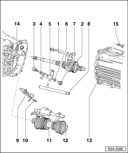
 
N34-0586
  • Selector rod with selector fork for 3rd and 4th gear
    • ◆ Dismantling and assembling
    • ◆ Replacing mounting bushes
      => Page 34-101
  • Input shaft
    • ◆ Dismantling and assembling => Page 35-1
    • ◆ Adjusting
    • ◆ Servicing input shaft bearings => Page 35-19
 
N34-0586
  • Left stop bolt - 40 Nm
    • ◆ The stop bolts are made of different materials for aluminium and magnesium gearboxes.
    • ◆ Allocation

=> Parts List

  • Washer
  • Relay shaft
    • ◆ Installation position => Fig. 34-101
  • Washer
  • Right stop bolt - 40 Nm
    • ◆ The stop bolts are made of different materials for aluminium and magnesium gearboxes.
    • ◆ Allocation

=> Parts List

 
N34-0586
  • Selector shaft
    • ◆ Installation position => Page 34-101
    • ◆ Replacing selector shaft sealing ring => Page 34-101
  • Detent segment
    • ◆ Installation position => Page 34-101
  • TORX-screw - 25 Nm
    • ◆ With shoulder to secure the detent segment spring
  • Selector rod with selector fork for 1st/2nd/5th and reverse gear
    • ◆ Dismantling and assembling => Page 34-101
    • ◆ Removing and installing ball sleeves => Fig. 34-107
 
N34-0586
  • Pinion shaft
    • ◆ Dismantling and assembling => Page 35-23
    • ◆ Adjusting
    • ◆ Servicing pinion shaft bearings => Page 35-23
  • Gearbox cover
    • ◆ Aluminium version: must only be fitted to an aluminium gearbox housing
    • ◆ Magnesium version: must only be fitted to a magnesium gearbox housing
    • ◆ Note identification markings
      =>Fig. 34-86
    • ◆ Apply thin coat of sealing paste AMV 188 001 02 to sealing surfaces
    • ◆ Removing and installing oil collector => Fig. 34-86
 
N34-0586
  • Gearbox housing
    • ◆ Aluminium version: must only be fitted to an aluminium gearbox cover
    • ◆ Magnesium version: must only be fitted to a magnesium gearbox cover
    • ◆ Note identification markings =>Fig.2
    • ◆ Allocate components according to gearbox code letters using Parts Catalogue=> Page 00-3 onwards
  • TORX-screw - 22 Nm
    • ◆ For aluminium gearboxes: black, M8 x 48, without washer
    • ◆ For magnesium gearboxes ä approx. 09.97: bright metal, M8 x 51, fit washer with each bolt
    • ◆ For magnesium gearboxes 09.97 ä (phased introduction): bright metal, different bolt lengths=> Fig.3
 
V34-1833

→ Fig.1    Removing and installing oil collector

Removing

  • ‒ Turn the oil collector -arrow- and then pull out.

Installing

  • ‒ Push oil collector into gearbox cover until it snaps in place.
    • ‒ Installation position: oil collector faces upwards in gearbox cover

 
N34-0619

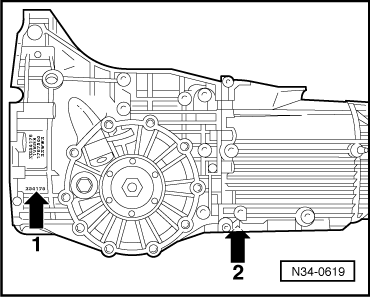
→ Fig.2    Gearbox cover and gearbox housing identification

The inscription >Mg Al 9 Zn 1< can be found in the vicinity of arrows 1 and 2 on gearboxes made of magnesium.

Mg = magnesium; additional data for production purposes.

The gearbox code letters also indicate whether a gearbox has a magnesium housing => from Page 00-3.

 
A34-0174

→ Fig.3    Locations of bolts for gearbox cover on gearboxes with magnesium housing , from approx. 09.97 ä

  •     1 -    Bright metal bolts, M8 x 48 without washer
  •     2 -    Bright metal bolts, M8 x 51 with captive washer

Note:

Only M8 x 51 bolts with captive washers are supplied as replacement parts; if necessary these can be used for all securing bolts on the gearbox cover.

Removing and installing input shaft ball bearing, multi-function sender, input shaft, pinion shaft, selector rods and gearbox co > < Removing and installing input shaft ball bearing and multi-function sender