audi Workshop Repair Guides

Audi Workshop Service and Repair Manuals

Removing and installing injectors > < Checking fuel pressure regulator and holding pressure
Motronic injection and ignition system (4-cyl.)
Servicing Motronic injection system
Testing injection quantity, leak-tightness and spray pattern of injectors
 
A24-0224

Test conditions

  • ● Fuel pressure OK; testing .

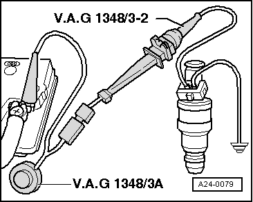
Testing injectors for leaks

  • ‒ → Pull vacuum hose -arrow- off fuel pressure regulator.
  • ‒ Unplug connectors from injectors and from Hall sender.
  • ‒ Unbolt fuel manifold from intake manifold and pull it upwards and off the intake manifold together with the injectors.
 
W00-0591
  • ‒ → Place the injector which is to be tested into a measuring glass from injection quantity tester V.A.G 1602.
  • ‒ Connect test box V.A.G 1598/31 to wiring harness for engine control unit. Do not connect to the engine control unit itself.
    => Page 24-10.
  • ‒ Bridge contacts 1 and 65 on the test box using test leads from adapter set V.A.G 1594 A. (This creates an earth connection to one side of the fuel pump relay coil.)
  • ‒ Switch on ignition.

Note:

Once the ignition has been switched on the fuel pump runs continuously, even if the engine is not running. This is because when the ignition is switched on the fuel pump relay receives a positive voltage supply via the central electrics. The negative voltage supply for the fuel pump relay comes via the cable bridge on the test box.

  • ‒ Check injectors for leaks (visual check). When the fuel pump is running, only 1 or 2 drops should escape per minute from each injector.
  • ‒ If the fuel loss is greater, switch off the fuel pump (turn off ignition) and renew the faulty injector.

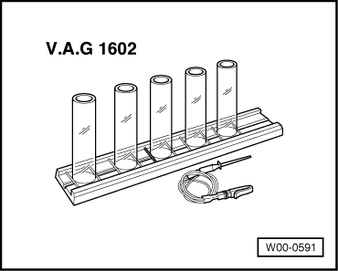
Checking injection quantity

  • ‒ Place the injector which is to be tested into a measuring glass from injection quantity tester V.A.G 1602.
 
A24-0079
  • ‒ → Connect one of the injector contacts to engine earth using test lead and crocodile clamp from V.A.G 1594 A.
  • ‒ Connect second injector contact to positive using remote control V.A.G 1348/3 A, adapter cable V.A.G 1348/3-2 and auxiliary cable.
  • ‒ Switch on ignition.
    • ‒ The fuel pump should run.
  • ‒ Activate remote control V.A.G 1348/3A for 30 seconds.
  • ‒ Carry out measurement on all injectors.
  • ‒ Once all four injectors have been actuated, place measuring glasses on a level surface.
  • Specification: 85...105 ml at each injector

If none of the injectors delivers the specified quantity:

  • ‒ Test fuel pressure => Page 24-20.

If only one injector fails to deliver the specified quantity:

  • ‒ Renew the affected injector.

Note:

When checking the injection quantity, also check the spray pattern. The spray pattern should be the same for all the injectors.

Installation of the fuel rail together with injectors is performed in the reverse sequence. The following points should be noted when installing:

  • ● Renew the O-rings at all opened connections. (When renewing the front O-ring, make sure not to remove the plastic cap from the injector head. The O-ring must be pulled off over the plastic cap.)
  • ● Moisten the O-rings with clean engine oil.
  • ● Check to make sure that the retainer clamps are properly seated.

Removing and installing injectors > < Checking fuel pressure regulator and holding pressure