audi Workshop Repair Guides

Audi Workshop Service and Repair Manuals

Servicing wheel bearing housing with bolted wheel bearing > < Servicing wheel bearing housing
Running gear, Front-wheel drive and four-wheel drive
Wheel bearing housing
Servicing wheel bearing housing with V.A.G 1459 B

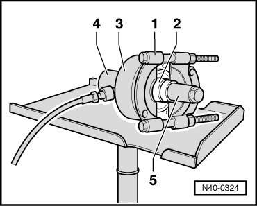
Instead of workshop press V.A.G 1290 A, use can also be made of hydraulic removal and installation tool for wheel bearing and wheel hub V.A.G 1459 B with accessory V.A.G 1459 B /2.

Advantages:

  • ‒ Wheel bearing housing need not be completely dismantled
  • ‒ Track rod end is not detached from wheel bearing housing and wheel alignment is thus not necessary

Special tools and workshop equipment required

  • ◆ V.A.G 1383 A Engine/gearbox lifter with universal gearbox support V.A.G 1359/2
  • ◆ V.A.G 1389 A/1 Foot-operated pump with high-pressure hose

If hand pump V.A.G 1389/1 is already available in workshop, this can be converted to a foot-operated pump.

Make use of conversion kit V.A.G 1389/3 for this purpose.
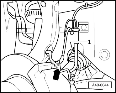
  • ◆ V.A.G 1459 B Hydraulic removal and installation tool for wheel bearing
    • ‒ Hollow plunger cylinder HKZ-15 with thrust pad E-0-204-T, hydraulic
    • ‒ Pins E-0-217+218
    • ‒ Special nut E-8-214
    • ‒ Thrust pad E-5
    • ‒ Thrust pad E-14-1
  • ◆ V.A.G 1459 B/2 Accessory set
    • ‒ Parting tool Kukko 17/2
    • ‒ Bell E-40
    • ‒ Thrust pad E-43
    • ‒ Thrust sleeve E-44-1
    • ‒ Thrust pad E-45
  • ◆ Parting tool Kukko 17/3

Removing

  • ‒ Slacken off hexagon bolt for drive shaft with vehicle standing on its wheels to avoid danger of accident.
  • ‒ Remove wheel and raise vehicle.
 
A40-0044
  • ‒ → Unscrew drive shaft from drive flange.
  •     1 -    Hexagon socket-head bolt or multi-point socket-head bolt
  • ‒ Pull wire of ABS speed sensor out of holder at brake caliper -arrow-.
  • ‒ Pull ABS speed sensor out of wheel bearing housing.
  • ‒ Detach brake carrier with brake caliper and attach with wire to body.
  • ‒ Remove brake disc and splash plate.
 
A40-0045
  • ‒ → Unscrew nut -1-, take out hexagon bolt and lift out both links -2-.

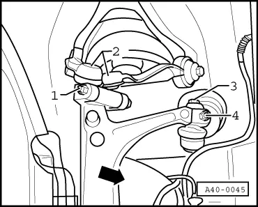
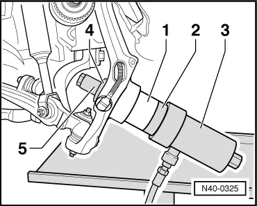
Slots in wheel bearing housing are never to be widened using a chisel or the like.

If hexagon bolt cannot be removed from wheel bearing housing, bolt and links -2- must be pressed out of wheel bearing housing .

  • ‒ Screw out hexagon bolt for drive shaft.
  • ‒ Swivel out wheel bearing housing.
  • ‒ Take drive shaft out of wheel bearing housing and tie up.

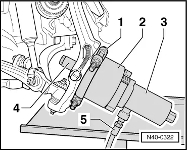
Note:

Place gearbox lifter V.A.G 1383/A in position (danger of accident caused by falling components on removing wheel hub and wheel bearing).

Removing wheel hub

 
N40-0322
  • ‒ → Insert parting tool -1- between wheel bearing housing and wheel hub and pre-tension.

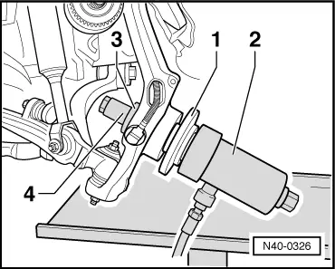
Installation position: Flat surfaces of edges point towards wheel hub

  • ‒ Fit bell -2-, hollow plunger cylinder -3- with pin and special nut -4-.
  • ‒ Remove wheel hub whilst holding tool.
  •     1 - Parting tool Kukko 17/2
  •     2 - Bell E-40
  •     3 - Hollow plunger cylinder HKZ-15
  •     4 - Special nut E-8-214 and pin
  •     5 - High-pressure hose with quick-release coupling

Removing wheel bearing

 
N40-0323
  • ‒ → Fit thrust pad -1- with collar facing bearing, thrust sleeve -2- with the four stepped inner diameters facing wheel bearing housing, hollow plunger cylinder -3- with pin and special nut -4-.
  • ‒ Remove wheel bearing by way of pump action.
  •     1 - Thrust pad E-5
  •     2 - Thrust sleeve E-44-1
  •     3 - Hollow plunger cylinder HKZ-15
  •     4 - Special nut E-8-214 and pin

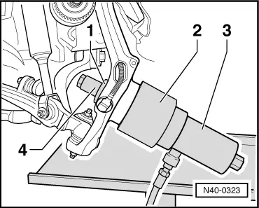
Detaching bearing inner race from hub

 
N40-0324
  • ‒ → Fit parting tool -1- behind bearing inner race -2-.

Installation position: Bevel of edges facing bearing inner race

  • ‒ Fit bell -3- and hollow plunger cylinder -4- with pin, screw on with special nut -5- and detach bearing inner race.
  •     1 - Parting tool Kukko 17/2
  • 2 - Bearing inner race
  •     3 - Bell E-40
  •     4 - Hollow plunger cylinder HKZ-15
  •     5 - Special nut E-8-214 and pin

Pressing in wheel bearing

Installation position: Large ID of wheel bearing facing outwards

 
N40-0325
  • ‒ → Place wheel bearing -1-, thrust pad -2- (position collar in bearing) and hollow plunger cylinder -3- with pin in position at wheel bearing housing.
  • ‒ Fit thrust pad -4- with bevels facing wheel bearing housing and special nut -5- from inside.
  • ‒ Press in wheel bearing by way of pump action.
  • 1 - Wheel bearing (different versions: ø 75 mm and ø 82 mm)
  •     2 - Thrust pad E-45 for wheel bearing (ø 75 mm) or thrust pad E-14-1 for wheel bearing (ø 82 mm)
  •     3 - Hollow plunger cylinder HKZ-15
  •     4 - Thrust pad E-43
  •     5 - Special nut E-8-214 and pin

Pressing in wheel hub

 
N40-0326
  • ‒ → Place wheel hub -1- and hollow plunger cylinder -2- with pin in position at wheel bearing.
  • ‒ Fit thrust pad -3- with collar facing special nut -4- from inside.
  • ‒ Press in wheel hub by way of pump action.
  •     1 - Wheel hub
  •     2 - Hollow plunger cylinder HKZ-15
  •     3 - Thrust pad E-5
  •     4 - Special nut E-8-214 and pin

Perform remaining installation operations in reverse order of removal.

Servicing wheel bearing housing with bolted wheel bearing > < Servicing wheel bearing housing