audi Workshop Repair Guides

Audi Workshop Service and Repair Manuals

Checking outer constant velocity joint > < Removing and installing drive shaft
Running gear, Front-wheel drive and four-wheel drive
Rear drive shaft
Servicing drive shaft

Special tools and workshop equipment required

  • ◆ 3207 Pressure spindle
  • ◆ 40-204 A Tensioner
  • ◆ VW 161 A Circlip pliers
  • ◆ VW 401 Pressure plate
  • ◆ VW 402 Pressure plate
  • ◆ VW 411 Press tool
  • ◆ VW 412 Press tool
  • ◆ VW 522 Support sleeve
  • ◆ V.A.G 1275 Hose clamp pliers
 
A42-0049

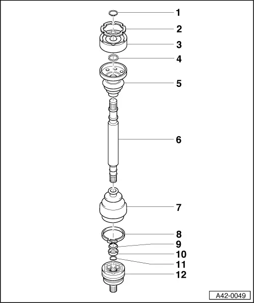
Quantities and type of grease

Constant velocity joints are filled with high-temperature grease.

=> Parts List

Grease

of which in:

Outer joint

Total quantity

Joint

Bellows

ø mm

[g]

[g]

[g]

89

90

40

50

Inner joint

ø mm

100

80

30

50

Re-grease joint if necessary on replacing boot.

  • Circlip
    • ◆ Always replace
    • ◆ Removing and fitting with circlip pliers VW 161 A => Fig.4
 
A42-0049
  • Gasket
    • ◆ Replace; pull off backing and bond into joint
  • Inner constant velocity joint
    • ◆ OD: 100 mm
    • ◆ Replace only as complete assembly
    • ◆ Pressing off => Fig.2
    • ◆ Pressing on => Fig. 3
    • ◆ Lubricating
    • ◆ Checking => Page 42-130
  • Dished washer
    • ◆ Installation position => Fig. 6
 
A42-0049
  • Boot for inner constant velocity joint
    • ◆ Check for cracks and abrasion
    • ◆ Drive off with mandrel
    • ◆ Checking inner constant velocity joint if boot damaged => Page 42-130
    • ◆ Coat sealing surface with D 454 300 A2 before attaching to constant velocity joint
    • ◆ Before fitting, align screw holes of inner constant velocity joint and inner boot
    • ◆ On assembly, boot/drive shaft sealing surfaces must be free from grease
  • Drive shaft
    • ◆ Same length on left and right
 
A42-0049
  • Boot for outer constant velocity joint
    • ◆ Check for cracks and abrasion and replace if necesssary
    • ◆ Checking outer constant velocity joint if boot damaged => Page 42-127
    • ◆ On assembly, boot/drive shaft/joint sealing surfaces must be free from grease
  • Clamp
    • ◆ Replace
    • ◆ Tensioning => Fig. 1
  • Dished washer
    • ◆ Large ø (concave side) makes contact with thrust ring
    • ◆ Installation position => Fig. 5
  • Spacer ring (plastic)
    • ◆ Installation position => Fig.5
 
A42-0049
  • Circlip
    • ◆ Replace
    • ◆ Insert in shaft groove
  • Outer constant velocity joint
    • ◆ OD: 89 mm
    • ◆ Replace only as complete assembly
    • ◆ Pressing off =>Fig. 7
    • ◆ Checking => Page 42-127
    • ◆ Installing: Drive onto shaft with plastic-headed hammer until circlip engages in annular groove of constant velocity joint
    • ◆ Lubricating => Page 42-118
 
V40-1132

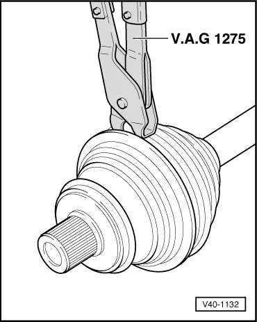
→ Fig.1    Tensioning hose clamp or clamp

 
V40-0222

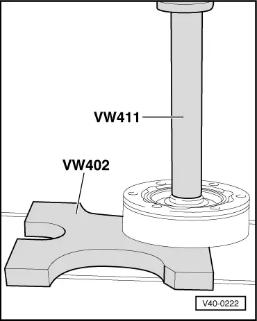
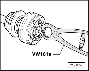
→ Fig.2     Pressing off inner constant velocity joint

Notes:

  • ◆ Use mandrel to drive off boot beforehand.
  • ◆ Support ball hub.

 
A42-0352

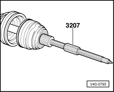
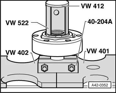
→ Fig.3    Pressing on inner constant velocity joint

Note:

Chamfer at ID of ball hub (splines) must face contact collar of drive shaft.

  • ‒ Press on joint as far as it will go.
  • ‒ Engage circlip.
 
V40-0003

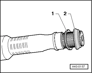
→ Fig.4    Removing/fitting circlip

 
A40-0157

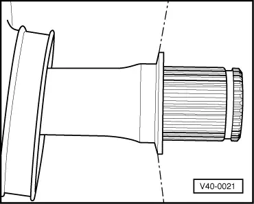
Fig.5    → Installation position of spacer ring and dished washer (wheel end)

  •     1 -    Dished washer
  •     2 -    Spacer ring (plastic)
 
V40-0021

→ Fig.6    Fitting dished washer in correct position

 
V40-0793

→ Fig.7    Pressing off outer constant velocity joint

  • ‒ Clamp drive shaft with soft jaws in vice.
  • ‒ Detach clamp and push back bellows.
  • ‒ Screw pressure spindle -3207- with M14 thread into joint pin until constant velocity joint is pressed off drive shaft.

Checking outer constant velocity joint > < Removing and installing drive shaft