| –
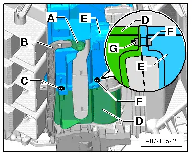
| Check the groove -A- at the left heater housing -F- and the tongue at the air conditioning unit -B- for damage. |

Note | If the groove -A- at the left heater housing -F- or the tongue at the air conditioning unit -B- is damaged, seal this area with silicone adhesive sealant D176 001 A3 for example → Electronic parts catalogue. |
| –
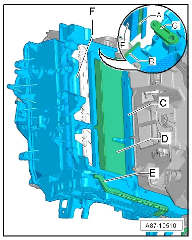
| Check the heat exchanger -C- and the evaporator -D- for contamination and clean these components if necessary. |
| –
| Check the foam seals at the heat exchanger -C- and at the supplementary air heater element -Z35- (or at the honeycomb element on vehicles with no -Z35-) for damage. |
| –
| Insert the grooves -A- at the left heater housing -F- in the tongues at the air conditioning unit -B- and slide the left heater housing -F- into the air conditioning unit. |
Note | On insertion, pay attention to the connecting rod to the right temperature flap -E- and the lever at the defrost flap -G- (as well as the lever at the centre left dash panel vent flap on vehicles with an air conditioner of the „Deluxe“ type) . |
| –
| Re-install all the other parts removed in reverse order. |
| –
| Switch on the ignition. |
Note | t
| During basic setting, control motor assignment and adaption are implemented on the basis of the arrangement in the series connection of the wiring. If the sequence is not as specified, the matching of the control motors and thus flap control will not be correct → Chapter (block diagram of air conditioner control motors). |
|
|
|
 Caution