audi Workshop Repair Guides

Audi Workshop Service and Repair Manuals

Removing and installing in-line ATF filter > < Removing and installing ATF lines - vehicles with 6-cyl. engine
Removing and installing ATF lines - vehicles with 8-cyl. engine
   
Removing and installing ATF lines - vehicles with 8-cyl. engine
Special tools and workshop equipment required
t  Support bracket -10 - 222 A-
t  Engine and gearbox jack -V.A.G 1383 A-
t  Used oil collection and extraction unit -V.A.G 1782-
t  Engine bung set -VAS 6122-
t  Engine support bracket, supplementary set -T40093-

   
Removing
  Note
→ Chapter „Rules for cleanliness when working on the dual clutch gearbox“.
–  Remove noise insulation panels -1- and -2- → General body repairs, exterior; Rep. gr.66.
  A10-11071
–  If fitted, remove bolts (left and right) -arrows- and detach heat shield -1-.
  A10-11173
–  Remove both front wheels.
–  Remove cover -1- for drive shaft from wheel housing (both sides).
  A10-10179
–  Remove lock carrier cover → General body repairs, exterior; Rep. gr.63.
  A63-10291
–  Remove bolts -arrows- and detach air duct -1- from air cleaner housing (left and right).
  A24-10805
–  Place used oil collection and extraction unit -V.A.G 1782- below connection.
–  Remove bolt -2- and detach ATF line.
–  Seal off open lines and connections with clean plugs from engine bung set -VAS 6122-.
  Note
t  For illustration purposes, the installation position is shown with the engine removed.
t  -Item 1- can be disregarded.
  A34-10641
–  Remove bolt -arrow- for ATF lines.
  A10-11272
–  Remove bolts -2- and -arrows- and detach retaining bracket with spring.
  Note
t  The bolt indicated by the top -arrow- also secures the ATF supply line to the gearbox.
t  -Item 1- can be disregarded.
  A26-10580
Vehicles with in-line ATF filter:
–  Place used oil collection and extraction unit -V.A.G 1782- below connection.
–  Pull off clip -1-, disconnect and detach ATF line.
–  Remove bolts -2 and 4- and detach ATF line -3- from gearbox.
–  Seal off open lines and connections with clean plugs from engine bung set -VAS 6122-.
  A37-11024
–  Remove bolt -1-.
  Note
Place a cloth below to catch escaping ATF.
–  Pull off retaining clip -arrow-, disconnect and detach ATF pipe/hose assembly.
  Note
Disregard -item 2- if not removing in-line ATF filter.
  A34-10658
Vehicles with exchangeable ATF filter -A-:
–  Place used oil collection and extraction unit -V.A.G 1782- below connection.
–  Pull off clip -1-, disconnect and detach ATF pipe/hose assembly (supply) -5-.
–  Remove bolt -4- and detach ATF supply line -2- from gearbox.
–  Detach ATF return line -3- from gearbox.
–  Seal off open lines and connections with clean plugs from engine bung set -VAS 6122-.
  A34-10872
Continued for all vehicles:
–  Switch off ignition and take out ignition key.
–  Disconnect earth wire -2- from battery terminal →  Electrical system; Rep. gr.27.
  A27-10141
–  Remove engine cover panel -arrows-.
  A10-11257
–  Set up support bracket -10 - 222 A- with adapters -T40093/6- on suspension turrets (left and right), as shown in illustration.
–  Hook spindles -10 - 222 A /11- onto engine lifting eyes.
–  Partly take up weight of engine via the spindles.
  A10-10817
–  Remove nut -arrow- on longitudinal member (right-side) and move earth wires clear.
  A10-11266
–  Unplug electrical connector -1- at headlight range control sender 1 -G233- and move wiring clear -arrow-.
  A10-10857
–  Remove bolt -1- for anti-roll bar on both sides.
  Note
-Items 2 and 3- can be disregarded.
  A40-10132
Vehicles with hydraulic power-assisted steering:
–  Remove nut -1- for hydraulic line for power steering.
  Note
-Arrows- can be disregarded.
  A40-10133
–  Unplug electrical connector -1- for servotronic solenoid valve -N119- and move wiring clear.
  Note
-Item 2- can be disregarded.
–  Move hydraulic power steering hose clear on subframe (left-side).
  A10-10869
Continued for all vehicles:
–  Detach intermediate steering shaft from steering box and telescope shaft upwards → Running gear, front-wheel drive and four-wheel drive; Rep. gr.48.
–  Move electrical wiring clear on subframe (right-side).
  A48-10005
–  Unplug electrical connector -1- from left electrohydraulic engine mounting solenoid valve -N144-.
–  Remove bolt -2- for engine mounting (left-side).
  A34-10677
–  Unplug electrical connector -2- from right electrohydraulic engine mounting solenoid valve -N145-.
–  Remove bolt -1- for engine mounting (right-side).
  A34-10678
–  Place used oil collection and extraction unit -V.A.G 1782- below connection.
–  Pull off retaining clip -1- and disconnect ATF line.
–  Seal off open lines and connections with clean plugs from engine bung set -VAS 6122-.
–  Remove nut -2-.
  A37-11023
–  Support subframe with engine and gearbox jack -V.A.G 1383 A- as shown in illustration.
  A10-10818
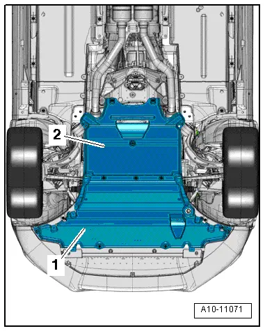
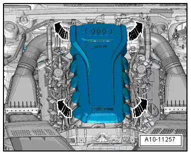
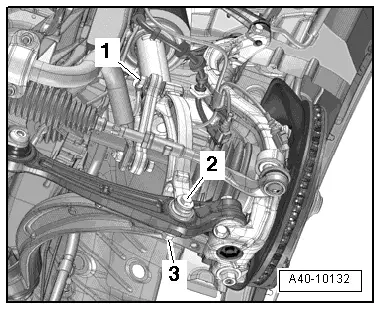
–  Mark installation position of subframe on longitudinal members with felt-tip pen.
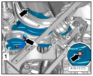
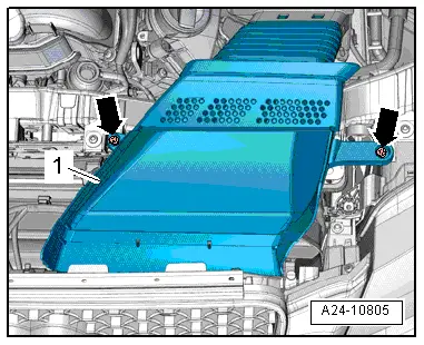
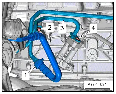
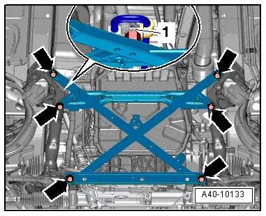
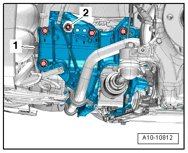
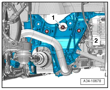
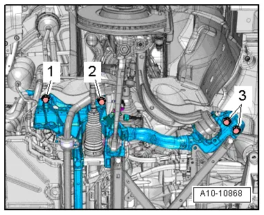
–  Unscrew subframe bolts -1, 2 and 3- on both sides in stages and in diagonal sequence.
  Caution
Risk of damage to parts of the running gear.
Do not let the vehicle down on the wheels if the gearbox mounting, steering box and subframe cross brace are not properly installed.
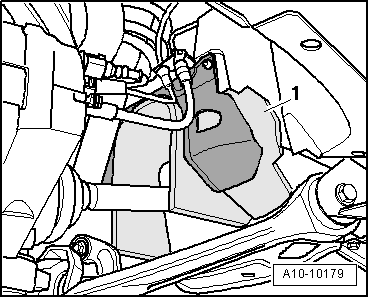
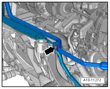
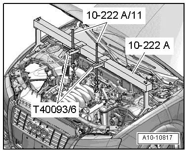
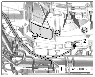
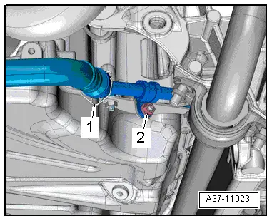
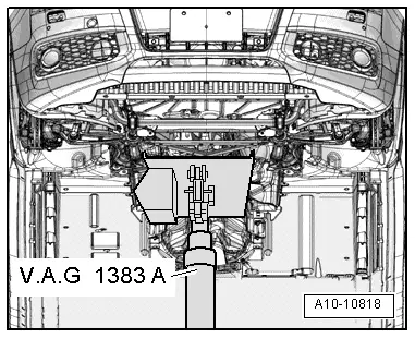
–  Using engine and gearbox jack -V.A.G 1383 A-, lower subframe only far enough to remove bottom ATF line; ensure sufficient clearance for hydraulic hoses (left-side) and electrical wiring (right-side).
Installing
Installation is carried out in reverse sequence; note the following:
l  Tightening torques → Chapter „ATF cooler, ATF lines and ATF filter“
  Note
Renew O-rings
  Caution
Risk of damage to gearbox
t  All plugs from engine bung set -VAS 6122- which were inserted in ATF lines and gearbox when dismantling must be removed.
t  If you forget to remove the plugs, the ATF cooling will be ineffective and the gearbox will be damaged.
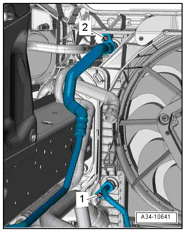
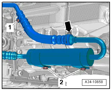
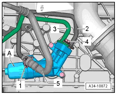
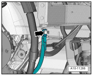
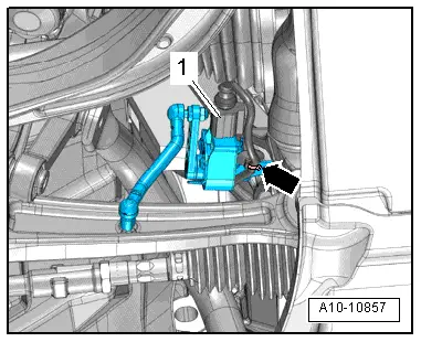
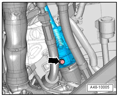
–  First press ATF lines onto gearbox and cooler by hand until they engage, then bolt on.
–  Press retaining clips onto ATF line connections and then pull to check that clips have engaged properly.
–  Check ATF level and top up as required → Chapter.
–  Align subframe on longitudinal members according to markings made before removal.
–  Tighten bolts for subframe to torque setting only, do not yet turn further (wait until wheel alignment has been carried out) → Running gear, front-wheel drive and four-wheel drive; Rep. gr.40.
  WARNING
Risk of accident if bolted connections are not tightened.
The vehicle must not be driven if the subframe mountings have not been fully tightened to the final setting.
–  Install anti-roll bar → Running gear, front-wheel drive and four-wheel drive; Rep. gr.40.
–  Install electrical wiring → Current flow diagrams, Electrical fault finding and Fitting locations.
–  Observe measures required after connecting battery → Electrical system; Rep. gr.27.
–  Secure intermediate steering shaft to steering box → Running gear, front-wheel and four-wheel drive; Rep. gr.48.
Vehicles with hydraulic power-assisted steering:
–  Install hydraulic line for power steering → Running gear, front-wheel drive and four-wheel drive; Rep. gr.48.
Continued for all vehicles:
–  Install wheel housing liners → General body repairs, exterior; Rep. gr.66.
–  Install front wheels and check wheel alignment → Wheels and tyres; Rep. gr.44.
  WARNING
Risk of accident if bolted connections are not tightened.
After completing wheel alignment, tighten bolts securing subframe to final setting.
–  Install noise insulation panels → General body repairs, exterior; Rep. gr.66.
  A10-10868

Removing and installing in-line ATF filter > < Removing and installing ATF lines - vehicles with 6-cyl. engine