| t
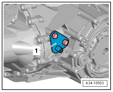
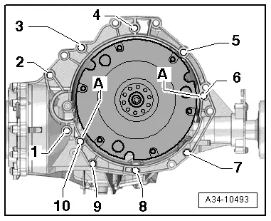
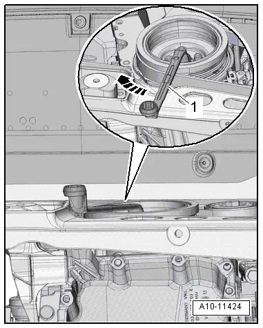
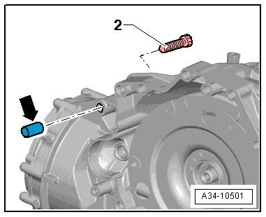
| Bolt -2- also secures the starter to the gearbox and has an additional spacer sleeve -arrow-. |
| t
| The spacer sleeve must be fitted between the starter and the gearbox. |

Caution | Overvoltage can cause irreparable damage to control units. |
| Do not use charger for boost starting. |
|
| –
| Check selector lever cable and adjust if necessary → Chapter. |
| –
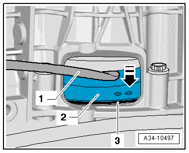
| Check ATF level and top up as required → Chapter. |
| –
| After performing repair work on gearbox, check gear oil level in front final drive and top up if necessary → Chapter. |

Note | t
| Tightening torques apply only to lightly greased, oiled, phosphated or black-finished nuts and bolts. |
| t
| Additional lubricant such as engine or gear oil may be used, but do not use graphite lubricant. |
| t
| Do not use parts which have been degreased. |
| t
| Tolerance for tightening torques is ± 15 %. |
|
|
|