
A4 Mk3
| Exploded view - dismantling and assembling gearbox |
| Removing and installing flange shaft (left-side), clutch module, end cover, side shaft, selector shaft and gearbox cover |
| Exploded view - removing and installing input shaft, output shaft, reverse gear wheel and selector plates / selector forks → Chapter |
| Dismantling and assembling gearbox - assembly sequence → Chapter |

| 1 - | Clutch module |
| q | Removing and installing → Chapter |
| q | Servicing with „Sachs“ version clutch → Chapter |
| q | Servicing with „LuK“ version clutch → Chapter |
| 2 - | Clutch release lever with release bearing and retaining spring |
| q | Removing and installing → Chapter |
| q | Dismantling and assembling → Chapter |
| 3 - | Bolt |
| q | 8 Nm |
| q | 2x |
| q | Apply locking fluid -AMV 185 101 A1- when fitting |
| 4 - | Retaining piece |
| q | Not fitted on all versions |
| q | Installation position: recess for bolts → Item faces towards clutch module |
 Note
Note| t | Discontinued as of 02.2008 |
| t | Is also omitted when new guide sleeve is installed → Item |
| 5 - | Guide sleeve |
| q | Remove any existing grease from guide sleeve |
| 6 - | Input shaft oil seal |
| q | Removing and installing → Chapter |
| 7 - | Circlip |
| q | Determining thickness → Fig. |
| q | Insert in circumferential groove in input shaft |
| 8 - | Gearbox housing |
| q | Removing and installing input shaft and output shaft with selector plates / selector forks → Chapter |
| q | Servicing → Chapter |
| q | Removing and installing differential → Chapter |
| 9 - | Oil drain plug |
| q | 45 Nm |
| 10 - | Bolt |
| q | 200 Nm |
| q | For output shaft |
| q | Apply locking fluid -AMV 185 101 A1- when fitting |
| 11 - | Sealing cap |
| q | With oil guide |
| q | For output shaft |
| q | Always renew |
| 12 - | Bolt |
| q | 10 Nm and then turn 45° further |
| q | Aluminium bolts (M8; 22 mm long) |
| q | 4x |
| q | Always renew |
| 13 - | Selector shaft with selector mechanism cover |
| q | Different versions are installed (with and without gearbox neutral position sender -G701- |
| q | Select correct version according to gearbox code letters → Electronic parts catalogue |
| 14 - | O-ring |
| q | Always renew |
| 15 - | Bolt |
| q | 20 Nm and then turn 30° further |
| q | Steel bolts (M8; 30 mm long) |
| q | 3x |
| q | Secures bearing mounting to gearbox cover |
| q | Apply locking fluid -AMV 185 101 A1- when fitting |
| 16 - | Gear detector switch -F208- |
| q | 20 Nm |
| 17 - | Side shaft |
| q | With spur gear |
| 18 - | Bolt |
| q | 150 Nm and then turn 90° further |
| q | Secures side shaft to pinion shaft |
| q | Always renew |
| q | Bolt head: twelve-point, 21 mm across flats |
| 19 - | Bolt |
| q | 15 Nm and then turn 90° further |
| q | Steel bolts (M8; 55 mm long) |
| q | 2x |
| q | Always renew |
| 20 - | Centre hex stud |
| q | 15 Nm and then turn 90° further |
| q | Steel studs (M8/M8; 38 mm long) |
| q | 2x |
| q | Not fitted on all gearboxes, in which case bolts are installed → Item |
| q | Always renew |
| 21 - | Bolt |
| q | 10 Nm and then turn 90° further |
| q | Aluminium bolts (M8; 35 mm long) |
| q | 9 or 11x |
| q | Always renew |
| 22 - | End cover |
| q | Servicing → Chapter |
| 23 - | Circlip |
| q | Determining thickness → Anchor |
| q | Fit in annular groove on output shaft |
| 24 - | Spur gear |
| q | Drive gear for side shaft / pinion shaft (spur gearing) |
| 25 - | Gearbox cover |
| q | Servicing → Chapter |
| 26 - | Bolt |
| q | 15 Nm and then turn 90° further |
| q | Steel bolt (M8; 50 mm long) |
| q | 1x |
| 27 - | Bolt |
| q | 10 Nm and then turn 90° further |
| q | Aluminium bolts (M8; 35 mm long) |
| q | 16x |
| q | Always renew |
| 28 - | Oil filler plug |
| q | 45 Nm |
| 29 - | Bolt |
| q | 10 Nm and then turn 45° further |
| q | Aluminium bolts (M8; 22 mm long) |
| q | Secures gearbox neutral position sender -G701- or sealing plug and sealing cap/selector shaft to gearbox cover |
| q | Not fitted on all versions |
| q | Always renew |
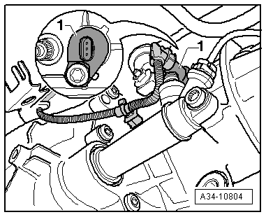
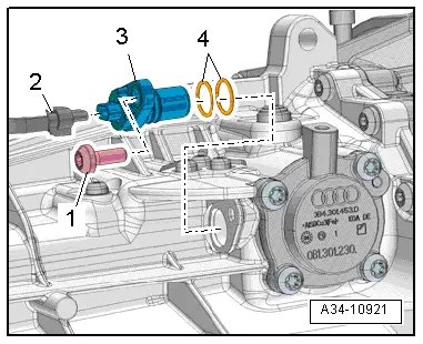
| 30 - | Gearbox neutral position sender -G701- or sealing plug |
| q | Gearbox neutral position sender for vehicles with start/stop system |
| q | Installation position → Fig. |
| q | Not fitted on gearbox with gear detection sensor -G604- → Fig. |
| q | Sealing plug is fitted in place of gearbox neutral position sender -G701- |
| q | Select correct version according to gearbox code letters → Electronic parts catalogue |
Note| If a sealing plug is fitted in place of the gearbox neutral position sender -G701-, it does not have to be removed when dismantling and assembling the gearbox. |
| q | Can be removed and installed with gearbox installed in vehicle → 6-speed manual gearbox 0B1, front-wheel drive; Rep. gr.34 |
| 31 - | O-ring |
| q | Always renew |
| q | Installed in gearboxes with gearbox neutral position sender -G701- or sealing plug |
| 32 - | Dowel sleeve |
| q | 2x |
| 33 - | Bolt |
| q | 15 Nm and then turn 45° further |
| q | Steel bolts (M8; 25 mm long) |
| q | 3x |
| 34 - | Flange shaft (left-side) |
| q | With mounting bracket |
|
|
|
|