audi Workshop Repair Guides

Audi Workshop Service and Repair Manuals

Exploded view - servicing end cover > < Removing and installing input shaft, output shaft, reverse gear wheel and selector plates/selector forks
Fitting sequence - dismantling and assembling gearbox
The end cover, side shaft, gearbox cover, input shaft and output shaft are removed and installed together with the internal gearbox selector mechanism.
  Note
t  The differential does not have to be removed in order to remove the above-mentioned components.
t  Refer to general repair instructions → Chapter.
   
Special tools and workshop equipment required
t  Drift sleeve -VW 244 B-
t  Thrust plate -40 -105-
t  Punch -3013-
t  Clamping sleeve -3116- is not required
t  Extractor -3349-
t  Extractor hook -T20143-

   
t  Assembly tool -T40041-
t  Thrust piece -T40174-
t  Gearbox support -T40206-
t  Separating tool -T40213-
t  Support -T40214-
t  Guide pin -T40216-

   
t  Hot air blower -V.A.G 1416-
t  Locking fluid -AMV 185 101 A1-
t  Sealing paste -AMV 188 001 02-
t  Grease for clutch plate splines -G 000 100-
t  Lubricating paste -G 000 150-
t  Sealing grease -G 052 128 A1-
Dismantling gearbox
  W00-0004
–  Place drip tray underneath.
–  Unscrew plug -arrow- and drain off gear oil.
  A34-10447
–  Attach gearbox support -T40206- to gearbox using bolts -arrows- and secure in assembly stand.
–  Remove clutch module → Chapter.
–  Put clutch module down carefully, e.g. on work bench.
  A34-10727
–  Remove clutch release lever -1- together with release bearing -2- and retaining spring -3-.
–  Screw out the bolts -4- and detach the guide sleeve -5-.
  A34-10847
–  If fitted, remove gearbox neutral position sender -G701--A-.
–  To do this, remove bolt -arrow- and pull sender out of sealing cap -B- for selector shaft.
  Note
t  Sealing cap -B- remains fitted.
t  If a sealing plug is fitted in place of the gearbox neutral position sender -G701-, it does not have to be removed when dismantling and assembling the gearbox.
  A34-10786
–  Remove bolts -1- and carefully lever off selector shaft cover -2-.
  A34-10461
–  Lift selector shaft slightly -arrow A- and pull it out -arrow B-.
  A34-10462
–  Lock the input and output shaft by moving the selector rods -1- to -4- in -arrow direction-.
  Note
So as not to damage the gearbox cover, place a cloth in the selector shaft opening between the tool and the housing wall.
  A34-10814
–  Pierce through centre of sealing cap -A- for output shaft and prise out in direction of -arrow-.
  A34-10593
–  Screw the bolt -A- out of the output shaft.
B - 12 mm Allen key
C - Torque wrench
–  Then move the selector plates to neutral position.
  A34-10815
–  Prise out input shaft oil seal.
  A39-10265
–  Then remove the circlip -1- in front of the input shaft ball bearing.
–  Remove the washer -2-.
  Note
t  If this circlip -1- cannot be removed, first detach the end cover and use a rubber-headed hammer to drive the input shaft forwards.
t  Always remove the washer -2- before pressing out the shaft group to stop it slipping into the groove for the circlip.
  A34-10812
–  Screw out the bolts -A- and -arrows- for the end cover -B- at the gearbox cover.
–  Detach the end cover -B- from the gearbox cover.
  A34-10839
–  Detach the roller bearing -1- from the output gear/spur gear mechanism.
–  Remove the circlip -2-.
  A34-10840
–  Then detach the output gear/spur gear mechanism -A- from the pinion shaft.
–  Then detach the input gear/spur gear mechanism -B- from the output shaft.
  A34-10841
–  Then position the gearbox in the assembly stand with the gearbox cover -D- facing upwards.
–  Screw out the bolts -A- (for bearing mounting attachment), the bolt -B- (for reverse shaft attachment) and the bolts -C- for the gearbox cover -D- at the gearbox housing -E-.
–  Detach the gearbox cover -D-, paying attention to the ball bearing on the input shaft (take care not to tilt the gearbox cover when detaching).
  Note
The ball bearing at the rear on the input shaft is mounted with a sliding fit in the gearbox cover.
  A34-10816
–  Remove the reverse gear wheel with reverse shaft -1-.
–  Detach the oil collector -2- from the bearing mounting -3--arrows A- and -arrow B-.
–  Detach the magnet -4- and the oil guide -5- from the gearbox housing.
  A34-10817
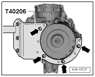
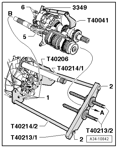
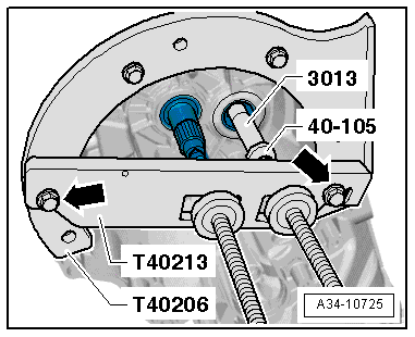
–  Attach separating tool -T40213- to gearbox support -T40206- with bolts -arrows-.
  Caution
Risk of damage to gears, shafts and bearings.
t  The input shaft and output shaft must be pressed out together.
t  It is permissible to turn the spindles alternately not more than one turn at a time when pressing out the shafts.
t  When taking out the shaft group, pay attention to the reverse gear synchroniser. It must not be allowed to slip off the output shaft.
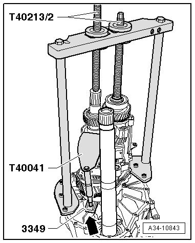
–  By turning spindles of separating tool -T40213- alternately one turn at a time, press input shaft and output shaft out of ball bearings in gearbox housing. When doing so, secure the shaft group to stop it dropping down (2nd mechanic).
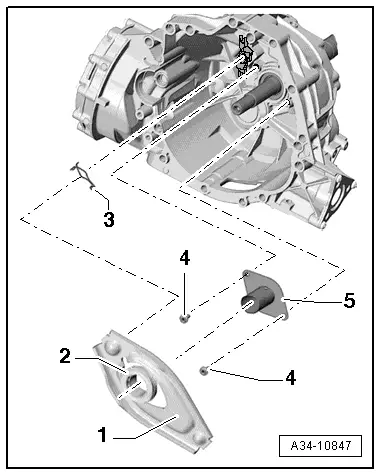
–  Detach the input and output shaft together with the selector fork cluster from the gearbox housing.
Assembling gearbox.
  Note
On replacing the gearbox cover, the input gear/spur gear mechanism, the tapered roller bearings for the input gear/spur gear mechanism or the end cover, the first step is to re-determine the shim for the pre-load of the input gear/spur gear mechanism tapered roller bearings → Chapter.
  A34-10725
To stop the reverse gear synchroniser sliding apart on inserting the shaft group, these components must be secured with an assembly tool as follows:
–  Fit the assembly tool -T40041- with an extractor hook from the extractor -3349- as shown.
–  Then position the assembly tool with the extractor hook at the reverse gear synchronising hub -A- and the 3rd gear wheel -C- and secure.
l  The spindle of the assembly tool -T40041- must not protrude at the extractor hook-arrow-.
l  The assembly tool must be positioned within the radius of the gearbox carrier -D-.
–  Use a small quantity of grease to affix the washer -B- to the reverse gear synchronising hub -A-.
  A34-10834
–  Secure the supports -T40214/1- and -T40214/2- at the gearbox housing as shown with the bolts -1- (total of 6x).
–  Secure the plate -T40213/1- with the bolts -2- at the supports -T40214/1 und T40214/2-.
–  Set the spindles -T40213/2- to the centre position.
–  Position the gearbox housing with the special tools fitted horizontally in the assembly stand as shown.
–  Warm the ball bearings in the gearbox housing with the hot air blower -V.A.G 1416-.
–  First guide the shaft group -5- beneath the plate -T40213/1- in -direction of arrow A-.
–  Then insert the shaft group with the input shaft in the gearbox housing -direction of arrow B-.
–  Hold the shaft group in this position and apply the two spindles -T40213/2- to the shafts. When doing so, the selector plates -6- must be aligned with the bearing points in the gearbox housing.
  Note
With certain gearboxes, the fit of the ball bearings with respect to the shafts is such that the shaft group can be pressed home by hand in the gearbox housing.
  A34-10842
–  Then position the gearbox in the assembly stand with the shaft group facing upwards.
–  If necessary, align the spindles -T40213/2- again with the shafts so that the spindles press centrally onto the shafts.
  Caution
Risk of damage to gears, shafts and bearings.
t  The input shaft and output shaft must be pressed in together.
t  It is permissible to turn the spindles alternately not more than one turn at a time when pressing in the shafts.
–  By way of the spindles -T40213/2-, alternately press in the input and output shaft one turn at a time until contact is made with the ball bearings.
  Note
t  Take care not to tilt the shafts when pressing in. Guide the selector plates into their bearing points in the gearbox housing.
t  Detach the assembly tool -T40041- before the extractor hook makes contact with the housing rib -arrow-.
t  Pay attention to the reverse gear synchroniser. The lugs of the intermediate ring must engage in the reverse gear synchronising hub.
–  Detach separating tool -T40213- and supports -T40214-.
  A34-10843
–  Insert the magnet -4- and the oil guide -5- in the gearbox housing.
–  Position the oil collector -2- on the lug -arrow B- of the bearing mounting -3- and then clip in at the bearing mounting -arrows A-.
–  Fit the reverse gear wheel with the reverse shaft -1-. When doing so, align the tapped hole -arrow C- with the mounting hole -arrow D- for the slave cylinder.
–  Check whether the 2 fitted pins for centring the gearbox cover/gearbox housing are in position in the gearbox housing or cover.
–  Apply sealing paste -AMV 188 001 02- evenly and not too thickly onto contact surfaces between gearbox housing and gearbox cover.
  A34-10817
–  Position the gearbox cover -D- on the gearbox housing -E- but do not yet screw in the bolts -C-.
–  Hand-tighten the bolt -B- in the reverse shaft.
–  Clean threads of bolts -A- with a wire brush. Then apply locking fluid -AMV 185 101 A1- and screw bolts hand-tight into bearing mounting.
–  Tighten the bolts -C- to torque.
–  Then tighten the bolts -A- and -B- to torque.
  A34-10816
–  Fit the washer -2- on the input shaft.
Determining circlip -1- for input shaft
–  Determine the thickest circlip that will just fit and install it. For part number refer to → Electronic parts catalogue.
  Note
Start with the thickest circlip.
The following circlips are available:
  A34-10812
Circlip thickness (mm)
1,952,102,25
2,002,15 
2,052,20 

   
–  Fit the input gear/spur gear mechanism -B- on the output shaft.
–  Fit the output gear/spur gear mechanism -A- on the pinion shaft.
  A34-10841
–  Fit the circlip -2-.
l  Installation position of roller bearing -1-: The larger inside diameter of the roller cage -arrow- must face the end cover.
–  Insert the roller bearing -1- in the output gear/spur gear mechanism.
–  Check whether the fitted pin for centring the gearbox cover/end cover is in position in the gearbox cover or end cover.
–  Apply sealing paste -AMV 188 001 02- evenly and not too thickly to the end cover contact surface at the gearbox cover.
  A34-10840
–  Fit the end cover -B- on the gearbox cover.
–  Fit bolts -A- and new bolts -arrows- and tighten to torque.
  A34-10839
–  Lock the input and output shaft by moving the selector plates -1- to -4- in -arrow direction-.
  Note
So as not to damage the gearbox cover, place a cloth in the selector shaft opening between the tool and the housing wall.
  A34-10814
–  Tighten the new bolt -A- for the output shaft to torque.
B - 12 mm Allen key
C - Torque wrench
–  Then move the selector plates to neutral position.
  A34-10815
–  Before installation, lightly oil outside circumference of new sealing cap -A- for output shaft, and drive in until flush.
  A34-10603
–  Lightly oil outer circumference of new oil seal for input shaft.
–  Pack space between sealing lip and dust lip half-full with sealing grease -G 052 128 A1-.
–  Use a thrust piece -T40174- to drive home the new oil seal, taking care to keep it straight.
–  Apply sealing paste -AMV 188 001 02- evenly and not too thickly to the selector mechanism cover sealing surface at the gearbox cover.
  A39-10328
–  Screw guide pin -T40216- onto selector shaft -1-.
  A34-10728
–  Lift selector shaft slightly -arrow B- and install it in gearbox -arrow A-.
  A34-10488
–  Position the selector shaft cover -2- in contact with the gearbox cover.
–  Clean the threads of the bolts -1- with a wire brush. Then apply locking fluid -AMV 185 101 A1- to the bolts, fit and tighten to torque.
–  Unscrew guide pin -T40216-.
  A34-10461
–  If previously fitted, insert gearbox neutral position sender -G701--A- with new O-ring in sealing cap -B- for selector shaft.
–  Clean the thread of the bolt -arrow- with a wire brush. Then apply locking fluid -AMV 185 101 A1- to the bolt, fit and tighten to torque.
  A34-10786
–  Clean and fit the guide sleeve -5-.
–  Clean threads of bolts -4- with wire brush. Then install bolts with locking fluid -AMV 185 101 A1- and tighten to specified torque → Item.
  Caution
Grating/creaking noises can occur when clutch is operated.
l  A lack of grease at the bearing points at the release bearing may cause creaking noise on pressing the clutch.
l  Apply a liberal amount of lubricating paste -G 000 150- to the bearing points at the release bearing → Fig..
l  Remove grease in bearing surface for guide sleeve: bearing on guide sleeve must be free of grease.
–  Install release lever -1- together with release bearing -2- and retaining spring -3- → Chapter.
  A34-10847
  Caution
Check version of needle bearing in dual-mass flywheel.
t  The needle bearing of the type where every 4th roller is missing -arrows- must always be renewed on vehicles with 4-cylinder TDI engine (except 125 kW TDI) → Chapter.
t  New needle bearings have the full number of rollers.
t  On all other vehicles the missing needle rollers do not mean that the needle bearing is defective. Do not renew the needle bearing.
–  Install clutch module and flange shaft (left-side) → Anchor.
–  Top up the gear oil in the manual gearbox and check the oil level → 6-speed manual gearbox 0B3, front-wheel drive; Rep. Gr.34.
  A30-10222

Exploded view - servicing end cover > < Removing and installing input shaft, output shaft, reverse gear wheel and selector plates/selector forks