
A5
| Renewing valve stem oil seals with cylinder head installed |

| Special tools and workshop equipment required |
| t | Spark plug socket and extension -3122 B- |
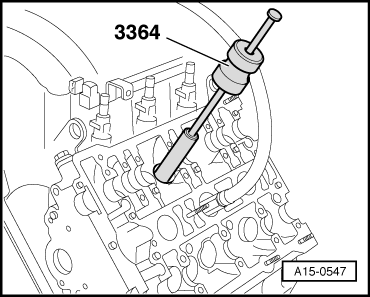
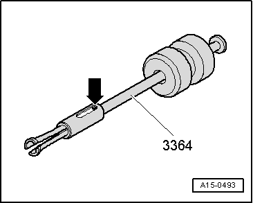
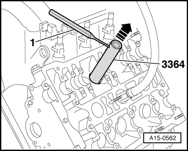
| t | Valve stem seal puller -3364- |
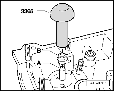
| t | Valve stem seal fitting tool -3365- |
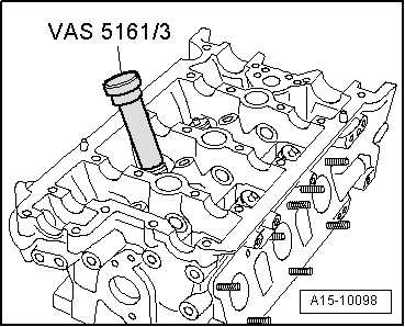
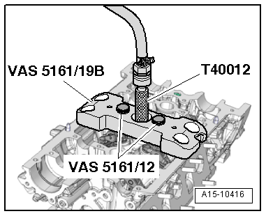
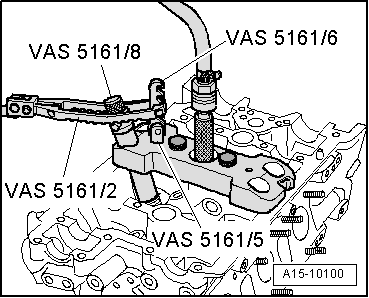
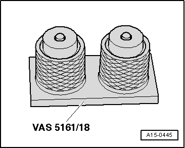
| t | Removal and installation device for valve cotters -VAS 5161- with guide plate -VAS 5161/19B- |
| t | Adapter -T40012- |
|
|
|
|
|
|
|
|
|
|
|
|
|
|
|
 Caution
|
|
|
|
|
|