audi Workshop Repair Guides

Audi Workshop Service and Repair Manuals

Removing and installing wheel bearing unit > < Exploded view of wheel bearing housing, wheel bearing unit
Removing and installing wheel bearing housing
  Note
t  Two different versions of wheel bearing housing were used at the start of production. The thickness of the steering arm on the wheel bearing housing is not the same on the two different versions. For correct version refer to → Electronic parts catalogue.
t  When renewing the wheel bearing housing, make sure that the thread of the pin on the track rod ball joint is long enough (the thread should project about 5 mm beyond the steering arm). If this is not the case, a new track rod ball joint with a longer pin thread must also be fitted; for correct version refer to → Electronic parts catalogue.
t  Distinguishing feature → Anchor
Special tools and workshop equipment required
   
t  Torque wrench -V.A.G 1331-
  W00-0427
t  Torque wrench -V.A.G 1332-
  W00-0428
t  Ring spanner insert -V.A.G 1332/10-
  W00-0953
t  or ring spanner insert -V.A.G 1332/7-
Removing
–  Slacken bolt securing drive shaft to wheel hub → Chapter.
–  Remove track control link → Chapter.
–  Detach bracket for brake line and electrical wiring from wheel bearing housing.
–  Remove front speed sensor → Rep. gr.45.
–  Detach brake caliper and secure to body so that weight of brake caliper does not stretch or damage brake hose or brake pipe.
–  Remove brake disc.
  W00-10096
–  Remove bolts -arrows- and take off splash plate -1-.
–  Unscrew nut on joint pin of guide link until it is flush with end of thread. Counterhold if necessary when loosening.
  A40-10404
Leave nut screwed on a few turns to protect threads on joint pin.
–  Press joint pin of guide link out of tapered seat using ball joint puller -T40010 A-.
  A40-10214
–  Detach bolt connection -1-.
–  Take both joint pins of upper links -2- out of wheel bearing housing.
Do not attempt to enlarge slots in wheel bearing housing using a chisel or similar.
–  Pull wheel bearing housing off drive shaft splines and remove.
  Note
t  Do not let the drive shaft hang down under its own weight, as otherwise excessive bending could damage the inner CV joint.
t  Tie up drive shaft to body with wire.
Installing
Installation is carried out in the reverse sequence. Note the following points:
Tightening torques → Chapter „Exploded view of wheel bearing housing, wheel bearing unit“
–  Push wheel bearing housing onto drive shaft splines.
  A40-10209
–  Fit both joint pins of upper links -2- into wheel bearing housing and insert bolt -1-.
–  Remove remaining adhesive from thread of joint pin on swivel joint and guide link.
–  Attach guide link to wheel bearing housing and tighten.
–  Install track control link → Chapter.
–  Attach track rod ball joint to wheel bearing housing → Chapter.
  Note
  A40-10209
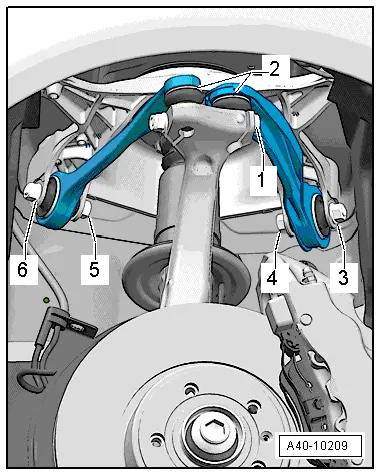
Press down upper links as far as possible while tightening nut.
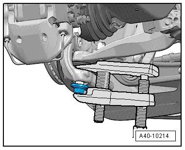
–  Tighten bolt connection -1- to specified torque.
–  Attach brake disc and brake caliper → Rep. gr.46.
–  Tighten bolt securing drive shaft to wheel hub → Chapter.
–  On vehicles with automatic headlight range control, carry out basic adjustment of headlights → Rep. gr.94.
–  If, on vehicles with electronic damping control, the vehicle level sender has been removed and refitted or the linkage detached, the reference position must be re-adapted → Chapter → Vehicle diagnostic tester.
–  If the reference position has been re-adapted on vehicles with lane departure warning, the lane departure warning control unit -J759- must be recalibrated → Chapter.
–  Secure wheel → Wheels and tyres; Rep. gr.44.
–  Check and adjust wheel alignment as required, see chart → Chapter.
  A40-10209

Removing and installing wheel bearing unit > < Exploded view of wheel bearing housing, wheel bearing unit