
Stratus Coupe V6-3.0L VIN H (2001)
Required Special Tools:
-
MB991223: Test Harness Set
-
MB991502: Scan Tool (MUT-II)
-
MB991529: Diagnostic Trouble Code Check Harness
STEP 1. Check the DTC.
Q: Does the DTC set when the ignition switch is turned to the "LOCK" (OFF) position?
YES: Carry out the troubleshooting by referring to Diagnostic Trouble Code Chart.
NO: Go to Step 2 <when using scan tool MB991502> or 3 <when using a voltmeter>.
STEP 2. Check the input signal (by using scan tool MB991502).
Check the input signals from the following switches.
-
Ignition switch (IG1)
-
Taillight switch
-
Headlight switch
CAUTION: To prevent damage to scan tool MB991502, always turn the ignition switch to the "LOCK" (OFF) position before connecting or
disconnecting scan tool MB991502.
1. Connect scan tool MB991502 to the data link connector.
2. Check that the tone alarm of scan tool MB991502 sounds when the input signal enters.
Q: Does the tone alarm of scan tool MB991502 sound when the input signal enters?
YES: Go to Step 4.
NO: Check the relevant input signal circuit.
STEP 3. Check the input signal (by using a voltmeter).
Check the input signals from the following switches.
-
Ignition switch (IG1)
-
Taillight switch
-
Headlight switch
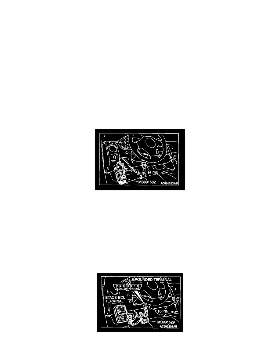
1. Use special tool MB991529 to connect a voltmeter between ground terminal 4 or 5 and ETACS-ECU terminal 9 of the data link connector.
2. Check that the voltmeter indicator deflects once when the input signal enters.