
Explorer Sport Trac 2WD V6-4.0L (2009)
Information Bus: Initial Inspection and Diagnostic Overview
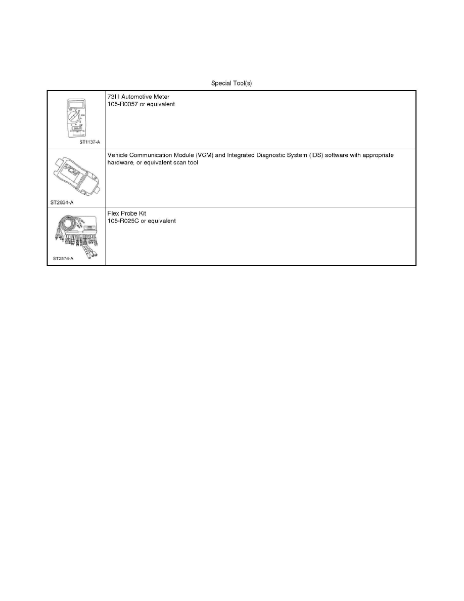
Special Tools Used With Diagnostics
Communications Network
Principles Of Operation
Communications Network
Principles of Operation
NOTE: The Smart Junction Box (SJB) is also known as the Generic Electronic Module (GEM).
Vehicle communication utilizes both Medium Speed (MS) and High Speed (HS) Controller Area Network (CAN) communications.CAN is a method for
transferring data among distributed electronic modules via a serial data bus.
The vehicle is equipped with 2 module communication networks:
-
Medium Speed Controller Area Network (MS-CAN)
-
High Speed Controller Area Network (HS-CAN)
Medium Speed Controller Area Network (MS-CAN)
The MS-CAN is a medium speed communication network that uses an unshielded twisted pair cable of data (+) and data (-) circuits. The data (+) and the
data (-) circuits are each regulated to approximately 2.5 volts during neutral or rested network traffic. As bus messages are sent on the data (+) circuit,
voltage is increased by approximately 1.0 volt. Inversely, the data (-) circuit is reduced by approximately 1.0 volt when a bus message is sent. Multiple
bus messages can be sent over the network CAN circuits allowing multiple modules to communicate with each other. The MS-CAN will not
communicate while certain faults are present, but will operate with diminished performance with other faults present. The MS-CAN may remain
operational when 1 of the 2 termination resistors are not present.
The MS-CAN operates at a maximum data transfer speed of 125 Kbps for bus messages and designed for general information transfer. The network will
remain operational, but at a degraded level, when certain circuit faults are present.
The following modules are on the MS-CAN:
-
Accessory Protocol Interface Module (APIM) (if equipped)
-
Audio Control Module (ACM)
-
Driver Seat Module (DSM) (if equipped)
-
HVAC module (if equipped)
-
Instrument Cluster (IC)