ford Workshop Repair Guides

Ford Workshop Service and Repair Manuals

Steering Column - 2.0L Duratec-ST (Zetec) > < Steering Column - Vehicles Built Up To: 03-2002
Steering Column - Steering Column—Vehicles Built From: 03/2002 Focus 1999 (08/1998-12/2004)
Disassembly and Assembly

Disassembly

  1. Remove the steering wheel.
    1. Disconnect the speed control electrical connector (if equipped).
    1. Remove the bolt.

  1. Remove the spacing collar.

  1. NOTE:
    NOTE:Make sure that the clockspring is not allowed to rotate. Secure it in the central position with a piece of suitable tape.
    Remove the clockspring.
    • Using a thin bladed screwdriver, release the two retaining clips.

  1. Remove the two multifunction switches.
    1. Depress the retaining tangs.
    1. Lift the switches upwards.

  1. Remove the passive anti-theft system (PATS) transceiver.
    • Remove the screw.

  1. Remove the ignition switch.
    • Release the clips.

  1. CAUTION:
    CAUTION:Never rotate the ignition switch camshaft from position 1 when the ignition lock cylinder has been removed. If the ignition lock mechanism is moved the security features are activated and will not be recovered.
    Remove the ignition switch lock cylinder.
    1. Insert and turn the ignition key to position 1.
    1. Using a thin bladed screwdriver, depress the detent.

Assembly

  1. CAUTION:
    CAUTION:Before removing the dummy ignition lock, the ignition switch camshaft must be rotated from the OFF position to position 1.
    CAUTION:
    CAUTION:If the dummy ignition lock is removed before the ignition switch camshaft is rotated to position 1 the security features will be activated and will not be recovered.
    NOTE:
    NOTE:This step is only required if assembling a new steering column.
    Using a suitable screwdriver rotate the ignition switch camshaft from the OFF position to position 1.

  1. CAUTION:
    CAUTION:Never rotate the ignition switch camshaft from position 1 when the dummy ignition lock has been removed. If the ignition switch camshaft is moved the security features are activated and will not be recovered.
    CAUTION:
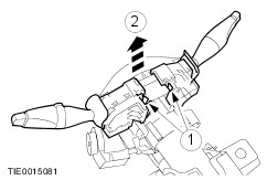
    CAUTION:Make sure that the ignition switch camshaft does not move from position 1 when the dummy ignition lock is moved to position 1. If the ignition switch camshaft is moved the security features are activated and will not be recovered.
    NOTE:
    NOTE:This step is only required if assembling a new steering column.
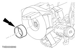
    Using a suitable Allen key, remove the dummy ignition lock.
    1. Insert the Allen key and turn the dummy ignition lock to position 1.
    1. Remove and discard the dummy ignition lock.

  1. Install the ignition switch lock cylinder.

  1. Install the ignition switch.

  1. Install the passive anti-theft system (PATS) transceiver.

  1. WARNING:
    WARNING:Make sure that the clockspring is centralized before installing it. Failure to follow this instruction may result in personal injury.
    Centralize the clockspring.
    1. Turn the clockspring in a COUNTERCLOCKWISE direction until a resistance is felt (approximately 2.5 turns from the central position).
    1. Turn the clockspring CLOCKWISE 2.5 turns until the arrow marked on the center of the clockspring aligns with the raised "V" section at the 12 o'clock position on the outer cover of the clockspring. The clockspring is now centralized.

  1. CAUTION:
    CAUTION:Make sure that the spacing collar is correctly located. Do not assemble if the spacing collar is missing.
    Install the clockspring.
    • Make sure both the retaining tangs lock into position on the steering column.

  1. Install the two multifunction switches.

  1. Install the steering wheel.
    1. Install the bolt.
    1. Connect the speed control electrical connector (if equipped).

Steering Column - 2.0L Duratec-ST (Zetec) > < Steering Column - Vehicles Built Up To: 03-2002