| Disassembly and Assembly Electric hand drill Stud extractor Materials Name Specification Constant velocity joint grease (High Temp) ESP-M1C207-A Disassembly Right-hand drive vehicles All vehicles | | -
Disconnect the speed control electrical connector (if equipped). | | | -
Remove the steering wheel. | | | -
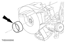
Remove the spacing collar. | | | -
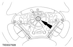
CAUTION:Make sure the clockspring is not allowed to rotate. Sercure in the central position with a piece of suitable tape. Remove the clockspring. - Using a thin bladed screwdriver, release the two retaining clips.
| | | -
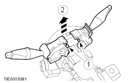
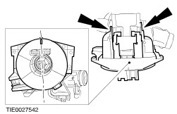
Remove the steering column multifunction switches. - Depress the retaining tangs.
- Lift the switches upwards.
| | | -
Remove the passive anti-theft system (PATS) transceiver. | | | -
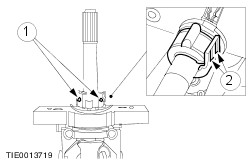
Remove the ignition switch. - Release the locking tangs.
| | | -
Remove the ignition switch lock cylinder. - Insert and turn the ignition key to position I.
- Using a thin bladed screwdriver depress the detent.
| Vehicles with stability assist | | -
Fully extend the steering column. - Release the locking lever.
- Extend the steering column.
| | | -
NOTE:The two halves of the steering column must be marked before separating to aid installation. Mark the two halves of the steering column. | All vehicles | | -
Remove the steering column bolt. | | | -
Separate the two halves of the steering column. | Vehicles with stability assist | | -
Remove the steering wheel rotation sensor clamp. - Remove the retaining screws.
- Depress the locking tangs.
| | | -
Remove the steering wheel rotation sensor retaining screws. | | | -
Remove the steering wheel rotation sensor. | Assembly Vehicles with stability assist | | -
WARNING:Do not install a new steering wheel rotation sensor if the locking pin has been removed. Failure to follow this instruction may result in personal injury. WARNING:Before fitting the steering wheel rotation sensor, make sure the rotor is in the correct position. Failure to follow this instruction may result in personal injury. Align the steering wheel rotation sensor. | | | -
WARNING:Make sure the steering wheel rotation sensor retaining screws are not over tightened. Failure to follow this instruction may result in personal injury. Install the steering wheel rotation sensor. | | | -
WARNING:Make sure the steering wheel rotation sensor clamp retaining screws are not over tightened. Failure to follow this instruction may result in personal injury. Install the steering wheel rotation sensor clamp. - Install the retaining screws.
- Apply Constant Velocity Joint Grease (High Temp)
| All vehicles | | -
NOTE:Make sure the steering column shafts are aligned correctly. Connect the two halves of the steering column. | | | -
WARNING:Make sure the breakaway capsules are located in the holes in the bracket. Failure to follow this instruction may result in personal injury. WARNING:Make sure the bolt is not over tightened. Failure to follow this instruction may result in personal injury. Tighten the steering column bolt. - Align the breakaway capsules.
- Tighten the steering column bolt.
| | | -
Install the ignition switch lock cylinder. - Insert the lock cylinder.
- Install the ignition switch lock.
| | | -
Install the ignition switch. | | | -
Install the PATS transceiver. | | | -
WARNING:Incorrect centralization may result in premature component failure. If in doubt when centralizing the clockspring, repeat the centralizing procedure. Failure to follow this instruction may result in personal injury. NOTE:After centralizing the clockspring make sure the clockspring is not allowed to rotate. Secure in the central position with a piece of suitable tape. Centralize the clockspring. - Turn the clockspring in a COUNTERCLOCKWISE direction until a resistance is felt (approximately 2.5 turns from the central position).
- Turn the clockspring CLOCKWISE 2.5 turns until the arrow marked on the center of the sliding contact aligns with the raised "V" section at the 12 o'clock position on the outer cover of the clockspring. The clockspring is now centralized.
| | | -
CAUTION:Make sure the spacing collar is correctly located. Do not assemble if the spacing collar is missing. Install the clockspring. - Make sure both the retaining tangs lock into position on the steering column.
| | | -
Install the steering column multifunction switches. | | | -
Remove the tape from the clockspring. | | | -
Install the steering wheel. | | | -
Connect the speed control electrical connector (if equipped). | Right-hand drive vehicles | | -
NOTE:The ignition lock shield retaining bolts are designed to shear at the specified torque. Install the ignition lock shield. | | | -
NOTE:The ignition lock shield retaining bolts are designed to shear at the specified torque. Install the ignition lock shield upper retaining bolt. | |