| In-vehicle Repair Special Tool(s) | | Pliers, Spark Plug Connector 303-622 (21-226) | Materials Name Specification Silicone grease ESE-M1C171-AA Removal All vehicles Vehicles built up to 12/2000 | | -
Remove the valve cover plate (if installed). - Unclip the fuel pipes.
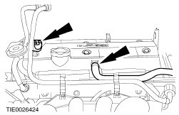
- Pull off the crankcase ventilation hose.
- Unclip the bracket of the evaporate emission (EVAP) canister vacuum line.
- Remove the bolts.
| | | -
CAUTION:Do not pull the cable when removing the spark plug connector. If necessary remove the ignition coil plug to avoid bending the cable. Turn the spark plug connector slightly before removing to loosen the seal. CAUTION:Pull off the spark plug connector in a straight movement. CAUTION:Do not damage the valve cover gasket as this cannot be renewed separately. Remove the valve cover straight upwards. - Pull off the plug of the cylinder head temperature (CHT) sensor.
- Disconnect the CHT leads from the spark plugs.
- Open the clip, clip off the CHT sensor electrical connector.
- Using Special Tool 303-622 for angled spark plug connectors.
- Remove three bolts from the upper timing belt cover.
- Remove the nuts.
| Vehicles built 12/2000 onwards | | -
Disconnect the crankcase ventilation (PCV) hose and the fuel supply and return line from the valve cover | | | -
CAUTION:Do not pull the cable when removing the spark plug connector. If necessary remove the ignition coil plug to avoid bending the cable. Turn the spark plug connector slightly before removing to loosen the seal. CAUTION:Pull off the spark plug connector in a straight movement. Disconnect the spark plug electrical connectors and unclip the wires from the valve cover. | | | -
Disconnect the cylinder head temperature (CHT) sensor electrical connector. | Installation Vehicles built up to 12/2000 | | -
CAUTION:Use a blunt object to apply the silicone grease to avoid damaging the spark plug connector seal. CAUTION:Push on the spark plug connector in a straight movement. NOTE:Coat the inside of the spark plug connector with silicone grease to a depth of 5-10 mm. Install the valve cover. - Install the nuts.
- Connect the CHT sensor electrical connector.
- Push on the spark plug electrical connector until it engages.
- Install the three bolts of the upper timing belt cover.
| | | -
Install the valve cover plate (if removed). - Install the bolts.
- Connect the positive crankcase ventilation (PCV) hose.
- Clip in the evaporative emission (EVAP) canister vacuum line bracket.
- Clip on the fuel pipes.
| Vehicles built 12/2000 onwards | | -
NOTE:Check the valve cover gasket for damage and install a new valve cover gasket as required. NOTE:First tighten the bolt position 1, 3-4 turns only. Install the valve cover. - Tighten the bolts in the sequence shown in two stages.
| | | -
Connect the cylinder head temperature (CHT) sensor electrical connector. | | | -
CAUTION:Use a suitable blunt object to avoid damage to the spark plug connector gasket. Coat the inside of the spark plug connector with silicone grease to a depth of 5-10 mm. Connect the spark plug electrical connectors and clip the wires to the valve cover. | | | -
Connect the PCV hose and the fuel supply and return line to the valve cover. | All vehicles Vehicles with front and rear power windows |