| In-vehicle Repair Removal | | -
Unclip the power steering reservoir and lay it to one side. | | | -
Slacken and remove the drive belt. | | | -
Remove the air cleaner with air intake hose. - Air intake hose.
- Disconnect the mass air flow sensor (MAF sensor) connector.
- Detach the PCV hose from the cylinder head cover.
| | | -
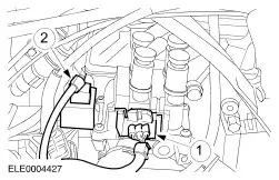
Disconnect the plug. - Ignition coil (EI).
- Condenser.
| | | -
Pull off the connector and the hose. - Idle air control (IAC) valve connector.
- Positive crankcase ventilation.
| | | -
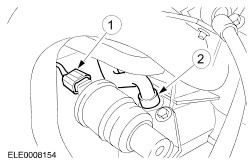
Detach the hoses and plugs. - Brake booster vacuum hose.
- Vacuum hose - fuel pressure control.
- Throttle position sensor (TP sensor) multiplug.
- Knock sensor (KS) plug.
| | | -
Unclip the wiring harness. | | | -
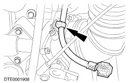
Detach the accelerator cable. - Pull off the clip.
- Unscrew the cable from the bracket.
| | | -
Unclip the hose bracket and lay it to one side. | | | -
Pull off the injector connectors and lay the engine wiring harness on the cover of the cylinder head cover. - Open the injector connector clips.
| | | -
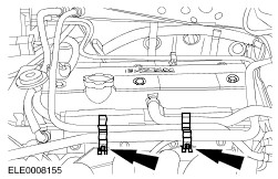
NOTE:The fuel feed line unions are white or are identified with a white ring. The fuel return line unions are red or are identified with a red ring. Detach the fuel pipes. | | | -
Detach the intake manifold. - Detach the oil dipstick tube bracket.
| | | -
Detach the carbon canister vacuum line. - Remove the intake manifold.
| Installation All vehicles | | -
Position the intake manifold and install the EVAP canister vacuum line. | | | -
Install the intake manifold using a new two-part gasket. - Install the oil dipstick tube bracket.
| | | -
CAUTION:Do not apply silicone grease to the injector O-rings, otherwise the injectors will become blocked. NOTE:Install new injector O-rings. Install the fuel rail. - Coat the injector O-rings with clean engine oil before installation.
| | | -
Push on the injection nozzle connector. | | | -
Clip the hose retainer in place. | | | -
Attach the accelerator cable. - Push on the clip.
- Screw the cable into the bracket.
| | | -
Clip the wiring harness in place. | | | -
Connect the hoses and connnectors. - Brake servo vacuum hose.
- Vacuum hose - fuel pressure control.
- TP sensor multiplug.
- KS plug.
| | | -
Push on the connector and the hose. - IAC valve connector.
- Crankcase ventilation.
| | | -
Connect the plug. - Ignition coil (EI).
- Condenser.
| | | -
Install the air filter with air intake hose. - Air intake hose.
- MAF connector.
- Attach the PCV hose to the cylinder head cover.
| | | -
Fit and tension the drive belt. | | | -
Clip on the power steering reservoir. | Vehicles with front and rear power windows |