| Removal and Installation Name Specification DOT 4 Brake Fluid SAM-6C9103-A Removal CAUTION:If brake fluid is spilt on the paintwork, the affected area must be immediately washed down with cold water. | | -
CAUTION:The brake fluid reservoir cap must not become contaminated. Remove the brake fluid reservoir cap. | | | -
NOTE:It will be necessary to carry out this step on both sides in order to completely drain the brake fluid reservoir. Drain the brake fluid reservoir. - Connect one end of a suitable piece of clear plastic pipe to the bleed nipple and place the other end into a suitable container.
- Loosen the bleed nipple.
- Depress the brake pedal until all the fluid is drained from the brake fluid reservoir.
- Tighten the bleed nipple.
| | | -
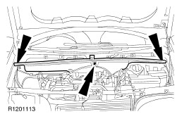
Remove the engine compartment noise reduction panel. | | | -
Detach the coolant expansion tank from the battery shield and position it to one side. - Disconnect the low level sensor electrical connector.
- Remove the coolant tank retaining bolts.
| | | -
Remove the battery side cover. - Detach the coolant expansion tank hose from the battery side cover.
- Remove the battery side cover retaining bolts.
| | | -
Disconnect the anti-lock brake system (ABS) module electrical connector. | | | -
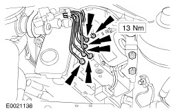
CAUTION:Cap the brake tubes to prevent fluid loss or dirt ingress. NOTE:Make a note of the position of the brake tubes, to aid installation. Disconnect the brake tubes from the hydraulic control unit (HCU). | | | -
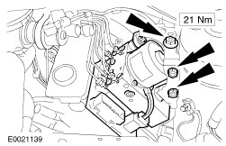
Detach the HCU and ABS module from the support bracket. | | | -
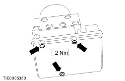
Remove the HCU to ABS module retaining bolts. | Installation | | -
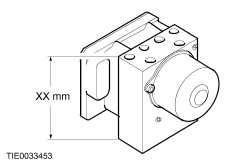
WARNING:Make sure that the correct HCU is installed. Failure to follow this instruction may result in personal injury. Measure the HCU body depth. - Vehicles equipped with anti-lock brake system (ABS): XX mm = 100 mm.
- Vehicles equipped with traction control: XX mm = 130 mm.
- Vehicles equipped with stability assist: XX mm = 135 mm.
| | | -
To install, reverse the removal procedure. | | |