| Disassembly Special Tool(s) | | Universal Flange Holding Wrench 205-072 (15-030A) | | | Socket, Cylinder Head Bolt 303-033 (21-002) | | | Locking Tool, Flywheel 303-254 (21-135) | | | Remover, Crankshaft Vibration Damper 303-338 (21-153B) | | | Remover/Installer, Hose Clamp 303-397 (24-003) | | | Mounting Stand 303-435 (21-187) | | | Mounting Bracket for 303-435 303-435-04 (21-064) | | | Mounting Plate for 303-435 303-435-12A (21-150B) | | | Holding Tool, Crankshaft 303-686 (21-244) | | | Wrench, Timing Belt Tensioner 303-1053 | | | Locking Tool, Timing Belt Tensioner 303-1054 | | | Holding Tool, Timing Belt Hydraulic Tensioner 310-084 (23-058) | General Equipment Piston ring compressor 4 mm drill bit 6 mm drill bit Disassembly All vehicles | | -
WARNING:Do not smoke or carry lighted tobacco or open flame of any type when working on or near any fuel related components. Highly flammable mixtures are always present and may ignite. Failure to follow these instructions may result in personal injury. Using a suitable washer between the engine and the special tool at the left hole and two M10 x 30 mm bolts, install the special tool. | | | -
Install the special tool. | | | -
NOTE:Install a new oil drain plug washer. Install the oil drain plug. | | | -
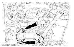
Using the special tool, disconnect the coolant hoses. | | | -
Disconnect the manifold absolute pressure (MAP) sensor and the intake air temperature (IAT) sensor electrical connector and remove the intake air pipe. | | | -
Disconnect the fuel temperature sensor electrical connector. | | | -
Disconnect the fuel lines from the fuel pump. | | | -
Disconnect the oil level sensor and the oil temperature sensor electrical connector. | | | -
Disconnect the engine coolant temperature (ECT) sensor electrical connector. | | | -
Disconnect the electrical connectors from the unit injectors. | | | -
Disconnect the power supply rail from the glow plugs. | | | -
Disconnect the camshaft position (CMP) sensor electrical connector. - Detach the CMP sensor electrical connector from the retaining bracket.
| | | -
Disconnect the crankshaft position (CKP) sensor electrical connector. - Detach the CKP sensor electrical connector from the retaining bracket.
| | | -
Disconnect the oil pressure switch electrical connector and the ground cable. | | | -
Disconnect the electrical connector from the generator. | | | -
Disconnect the battery positive cable from the generator. | | | -
Remove the engine wiring loom from the engine. | | | -
Remove the accessory drive belt tensioner. | | | -
Remove the power steering, air conditioning (A/C) compressor and generator bracket. | | | -
Remove the vacuum reservoir. | | | -
Remove the thermostat housing and the thermostat. | | | -
Remove the oil level indicator and tube. | | | -
Disconnect the turbocharger oil supply line from the oil filter housing. - Detach the oil supply line from the cylinder block.
| | | -
Disconnect the turbocharger oil supply line from the turbocharger. - Detach the turbocharger supply line from the intake manifold.
| | | -
Remove the coolant distribution tube. | | | -
Remove the oil filter housing. | | | -
Remove the coolant outlet housing. | | | -
Remove the vacuum and fuel pump. | | | -
Remove the turbocharger intake pipe and disconnect the positive crankcase ventilation (PCV) hose from the valve cover. | | | -
Using the special tool, remove the charge air cooler intake pipe from the turbocharger. | | | -
Remove the charge air cooler intake pipe bracket. | | | -
Remove the exhaust gas recirculation (EGR) tube. | | | -
Remove the intake manifold. | | | -
Remove the exhaust heat shield. | | | -
Disconnect the turbocharger oil return tube from the engine block. | | | -
Remove the turbocharger bracket retaining bolt. | | | -
Remove the exhaust manifold and turbocharger assembly. | | | -
Remove the engine support plate. | | | -
Remove the timing belt upper cover. | | | -
Remove the crankshaft pulley. | | | -
Remove the timing belt center cover. | | | -
Remove the timing belt lower cover. | | | -
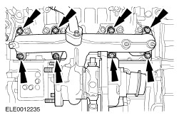
Remove the valve cover (13 bolts). - Discard the gasket if damaged.
| Vehicles with hydraulic timing belt tensioner | | -
Slacken the timing belt. - Loosen the timing belt tensioner retaining nut.
- Using the special tool, rotate the timing belt tensioner cam counterclockwise until the special tool can be inserted.
- Using the special tool, slacken the timing belt by rotating the timing belt tensioner cam clockwise.
| | | -
Remove the timing belt tensioner. | | | -
NOTE:Remove the timing belt from the coolant pump first. Remove the timing belt. | | | -
Remove the timing belt tensioner pulley. | Vehicles with mechanical timing belt tensioner | | -
Slacken the timing belt. - Loosen the timing belt tensioner retaining nut.
- Using the special tool, rotate the timing belt tensioner cam counterclockwise until the special tool can be inserted.
- Using the special tool, rotate the timing belt tensioner cam clockwise until it stops and tighten the retaining nut finger tight.
| | | -
NOTE:Remove the timing belt from the coolant pump first. Remove the timing belt. | | | -
Remove the timing belt tensioner. | All vehicles | | -
Remove the camshaft pulley. - Loosen the camshaft pulley center bolt by two turns.
- Remove the camshaft pulley.
| | | -
Using the special tool and three M8 x 70 mm bolts, remove the camshaft pulley hub. | | | -
Remove the timing belt rear cover. | | | -
CAUTION:Loosen the bolts in the sequence shown. Using the special tool, remove the cylinder head. - Discard the gasket and the bolts.
| | | -
Remove the clutch disc and pressure plate. | | | -
CAUTION:Do not bend the adapter plate. Using the special tool, remove the flywheel and the adapter plate. | | | -
NOTE:Do not discard the crankshaft timing pulley bolt at this stage, it will be required during assembly. Using the special tool, remove the crankshaft timing pulley. | | | -
Remove the crankshaft front seal carrier. | | | -
Remove the oil pump chain tensioner, the oil pump chain sprocket and the oil pump chain. | | | -
Remove the crankshaft rear seal carrier. - Discard the crankshaft rear seal and the crankshaft rear seal carrier.
| | | -
CAUTION:The upper bearing shell of the connecting rod (facing the piston) is made of a special material and marked with a black line. This line may not be recognizable at used bearing shells. Therefore do not mix-up the bearing shells during removal. If necessary mark the bearing shells. NOTE:Mark the connecting rod bearing caps and the connecting rods in accordance to the cylinder to which they belong and keep them in order for installation. Remove the pistons. - Remove the connecting rod bearing caps.
- Remove the pistons.
- Remove the bearing shells.
| | | -
NOTE:Keep the crankshaft bearing caps and bearing shells in order for installation. Remove the crankshaft. | | | -
Remove the engine speed sensor ring. | | | -
Remove the piston cooling oil spray nozzles (four). | |