| Installation Special Tool(s) | | Lifting Bracket, Engine 303-122 (21-068 A) | | | Support Bar, Engine 303-290 (21-140) | | | Adapter for 303-290 303-290-02 (21-140-02) | | | Adapter for 303-290 303-290-04 (21-140-04) | General Equipment Transmission jack Retaining straps Materials Name Specification Manual transmission fluid WSD-M2C200-C 2 Washers (30 mm diameter, 3 mm thickness) Anti-seize grease SAM-1C9107-A | | -
Install the transaxle left-hand retaining bolts. | | | -
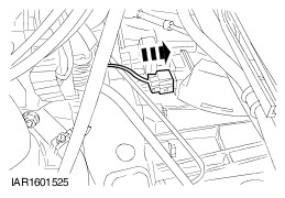
Connect the vehicle speed sensor (VSS) electrical connector. | | | -
Install the transaxle right-hand retaining bolts. | | | -
Install the transaxle upper retaining bolts. | | | -
Attach the coolant pipe to the transaxle. | | | -
Install the engine rear mount bracket. | | | -
NOTE:Do not tighten the engine rear mount retaining bolts and nut at this stage. Install the engine rear mount. - Install the bolt.
- Install new bolts and a new nut.
| | | -
NOTE:Do not tighten the engine front mount retaining bolts and nut at this stage. Install the engine front mount. - Install the bolts.
- Install the nut.
| | | -
Install the engine support insulator. - Tighten the retaining bolt.
- Tighten the bolt in two stages.
| | | -
Tighten the engine rear mount retaining nut and bolts. - Tighten the bolt.
- Tighten the bolts and the nut in two stages.
- Tighten the bolts in two stages.
| | | -
Tighten the engine front mount retaining bolts and nut. - Tighten the bolts.
- Tighten the nut.
- Connect the engine ground cable to the bolt.
| | | -
Remove the special tools. | | | -
Connect the reversing light switch electrical connector. | | | -
CAUTION:If brake fluid is spilt on the paintwork, the affected area must be immediately washed down with cold water. NOTE:Make sure the spring clip is correctly installed. Connect the clutch slave cylinder pressure pipe to the transaxle. | | | -
Attach the gearshift cables to the transaxle. | | | -
CAUTION:Support the halfshaft. The inner joint must not be bent more than 20 degrees. The outer joint must not be bent more than 50 degrees. CAUTION:Do not damage the halfshaft oil seal. CAUTION:Make sure that the snap ring is correctly seated. Attach the left-hand halfshaft to the transaxle. | | | -
CAUTION:Support the halfshaft. The inner joint must not be bent more than 20 degrees. The outer joint must not be bent more than 50 degrees. CAUTION:Do not damage the halfshaft oil seal. NOTE:Install a new center bearing locknuts. Attach the right-hand halfshaft with the intermediate shaft to the transaxle. | | | -
Attach the starter motor cable bracket to the transaxle. | | | -
Connect the generator positive cable to the starter motor. - Install the protective cap.
- Connect the starter motor electrical solenoid connector.
| | | -
Attach the heated oxygen sensor (HO2S) wiring harness to the transaxle. | | | -
CAUTION:Never use jointing compound forward of the catalytic converter. NOTE:Coat the catalytic converter bolts with anti-seize grease. NOTE:Install a new gasket and bolts. Attach the exhaust flexible pipe to the catalytic converter. | | | -
WARNING:Install a new tie-rod end retaining nut. Failure to follow this instruction may result in personal injury. Attach the left-hand tie-rod end to the wheel knuckle. - Tighten the nut in two stages.
| | | -
Attach the lower arm to the wheel knuckle on both sides (left-hand side shown). | | | -
Install the engine undershield. | | | -
Install the battery tray. - Attach the wiring harness rail to the battery tray.
- Attach the coolant hose to the battery tray.
| | | -
Install the battery side cover. - Attach the cooling system degas hose to the battery side cover.
- Attach the engine wiring harness electrical connector to the battery side cover.
| | | -
Connect the electrical connectors. - Connect the engine wiring harness electrical connector.
- Connect the engine coolant level sensor electrical connector.
| | | -
Connect the battery positive cable to the battery terminal clamp. | | | -
Install the air cleaner outlet pipe body. | | | -
With the vehicle on a level surface fill the transaxle until the oil level is just below the bottom of the filler hole. | | |