| PINPOINT TEST A : THE SPEED CONTROL IS INOPERATIVE |
| TEST CONDITIONS | DETAILS/RESULTS/ACTIONS |
| A1: CHECK THE PEDAL POSITION SWITCHES USING WDS |
| | 1 Using WDS Cruise control test, check the operation of the clutch pedal position (CPP) switch (if equipped) and brake pedal position (BPP) switch. |
| | Are the pedal position switches working correctly? Yes No The CPP switch is inoperative. Vehicles with 1.9L Diesel engines, GO to A12. The BPP switch is inoperative. Vehicles with 1.9L Diesel engines, GO to A16. |
| A2: CHECK FOR POWER AND GROUND TO THE STEERING WHEEL SWITCHES AND STEERING WHEEL SWITCH CONTROL MODULE |
| | 1 Check the function of the vehicle horn. |
| | 2 Ignition switch in position II. |
| | 3 Press each of the vehicle horn switches in turn. |
| | Does the vehicle horn sound? Yes No |
| A3: CHECK FOR POWER TO THE INSTRUMENT CLUSTER SPEED CONTROL ILLUMINATION |
| | 1 Check the function of the steering wheel speed control ON switch. |
| | 2 Operate the steering wheel speed control ON switch. |
| | Is the instrument cluster speed control illumination on? Yes Vehicles with 1.9L Diesel engines, GO to A4. No |
| A4: CHECK THE STEERING WHEEL SWITCH CONTROL MODULE TO PCM CIRCUIT FOR OPEN |
| | 1 Disconnect Steering wheel switch control module C544. |
| | 2 Disconnect PCM C52b. |
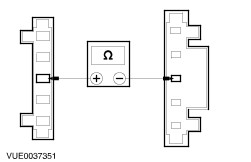
| | 3 Measure the resistance between the steering wheel switch control module C544 pin 4, (BK/WH), harness side and PCM C52b pin 14, (BK/WH), harness side. |
| | Is the resistance less than 5 ohms? Yes No REPAIR the circuit. TEST the system for normal operation. |
| A5: CHECK THE STEERING WHEEL SWITCH CONTROL MODULE TO PCM SET CIRCUIT FOR OPEN |
| | 1 Measure the resistance between the steering wheel switch control module C544 pin 8, (RD), harness side and PCM C52b pin 44, (RD), harness side. |
| | Is the resistance less than 5 ohms? Yes No REPAIR the circuit. TEST the system for normal operation. |
| A6: CHECK THE STEERING WHEEL SWITCH CONTROL MODULE TO PCM CAN CIRCUIT FOR OPEN |
| | 1 Measure the resistance between the steering wheel switch control module C544 pin 14, (GY), harness side and PCM C52b pin 46, (GY), harness side. |
| | Is the resistance less than 5 ohms? Yes No REPAIR the circuit. TEST the system for normal operation. |
| A7: CHECK THE STEERING WHEEL SWITCH CONTROL MODULE TO PCM RES CIRCUIT FOR OPEN |
| | 1 Measure the resistance between the steering wheel switch control module C544 pin 16, (BU/GY), harness side and PCM C52b pin 45, (BU/GY), harness side. |
| | Is the resistance less than 5 ohms? Yes No REPAIR the circuit. TEST the system for normal operation. |
| A8: CHECK THE STEERING WHEEL SWITCH CONTROL MODULE TO PCM CIRCUIT FOR OPEN |
| | 1 Disconnect Steering wheel switch control module C544. |
| | 2 Disconnect PCM C51b. |
| | 3 Measure the resistance between the steering wheel switch control module C544 pin 4, (BK/WH), harness side and PCM C51b pin 38, (BK/WH), harness side. |
| | Is the resistance less than 5 ohms? Yes No REPAIR the circuit. TEST the system for normal operation. |
| A9: CHECK THE STEERING WHEEL SWITCH CONTROL MODULE TO PCM SET CIRCUIT FOR OPEN |
| | 1 Measure the resistance between the steering wheel switch control module C544 pin 8, (BU/BN), harness side and PCM C51b pin 57, (BU/BN), harness side. |
| | Is the resistance less than 5 ohms? Yes No REPAIR the circuit. TEST the system for normal operation. |
| A10: CHECK THE STEERING WHEEL SWITCH CONTROL MODULE TO PCM CAN CIRCUIT FOR OPEN |
| | 1 Measure the resistance between the steering wheel switch control module C544 pin 14, (BK/YE), harness side and PCM C51b pin 76, (BK/YE), harness side. |
| | Is the resistance less than 5 ohms? Yes No REPAIR the circuit. TEST the system for normal operation. |
| A11: CHECK THE STEERING WHEEL SWITCH CONTROL MODULE TO PCM RES CIRCUIT FOR OPEN |
| | 1 Measure the resistance between the steering wheel switch control module C544 pin 16, (BU), harness side and PCM C51b pin 75, (BU), harness side. |
| | Is the resistance less than 5 ohms? Yes No REPAIR the circuit. TEST the system for normal operation. |
| A12: CHECK POWER TO THE CPP SWITCH |
| | 1 Disconnect CPP switch C356. |
| | 2 Ignition switch in position II. |
| | 3 Measure the voltage between the CPP switch C356 pin 1, (BK/YE), harness side and ground. |
| | Is the voltage greater than 10 volts? Yes No REPAIR the circuit. TEST the system for normal operation. |
| A13: CHECK THE CPP SWITCH CIRCUIT FOR OPEN |
| | 1 Ignition switch in position 0. |
| | 2 Disconnect PCM C52b. |
| | 3 Measure the resistance between the CPP switch C356 pin 2, (WH/RD), harness side and PCM C52b pin 66, (WH/RD), harness side. |
| | Is the resistance less than 5 ohms? Yes No REPAIR the circuit. TEST the system for normal operation. |
| A14: CHECK POWER TO THE CPP SWITCH |
| | 1 Disconnect CPP switch C154. |
| | 2 Ignition switch in position II. |
| | 3 Measure the voltage between the CPP switch C154 pin 1, (BK), harness side and ground. |
| | Is the voltage greater than 10 volts? Yes No REPAIR the circuit. TEST the system for normal operation. |
| A15: CHECK THE CPP SWITCH CIRCUIT FOR OPEN |
| | 1 Ignition switch in position 0. |
| | 2 Disconnect PCM C51b. |
| | 3 Measure the resistance between the CPP switch C154 pin 2, (BK/WH), harness side and PCM C51b pin 39, (BK/WH), harness side. |
| | Is the resistance less than 5 ohms? Yes No REPAIR the circuit. TEST the system for normal operation. |
| A16: CHECK POWER TO THE BPP SWITCH |
| | 1 Disconnect BPP switch C354. |
| | 2 Ignition switch in position II. |
| | 3 Measure the voltage between the BPP switch C354 pin 2, (BK/YE), harness side and ground. |
| | Is the voltage greater than 10 volts? Yes No REPAIR the circuit. TEST the system for normal operation. |
| A17: CHECK THE BPP SWITCH CIRCUIT FOR OPEN |
| | 1 Ignition switch in position 0. |
| | 2 Disconnect PCM C52b. |
| | 3 Measure the resistance between the BPP switch C354 pin 3, (WH/YE), harness side and PCM C52b pin 65, (WH/YE), harness side. |
| | Is the resistance less than 5 ohms? Yes No REPAIR the circuit. TEST the system for normal operation. |
| A18: CHECK POWER TO THE BPP SWITCH |
| | 1 Disconnect BPP switch C153. |
| | 2 Ignition switch in position II. |
| | 3 Measure the voltage between the BPP switch C153 pin 2, (BK), harness side and ground. |
| | Is the voltage greater than 10 volts? Yes No REPAIR the circuit. TEST the system for normal operation. |
| A19: CHECK THE BPP SWITCH CIRCUIT FOR OPEN |
| | 1 Ignition switch in position 0. |
| | 2 Disconnect PCM C51b. |
| | 3 Measure the resistance between the BPP switch C153 pin 3, (WH/YE), harness side and PCM C51b pin 55, (WH/YE), harness side. |
| | Is the resistance less than 5 ohms? Yes No REPAIR the circuit. TEST the system for normal operation. |
| A20: CHECK FOR POWER TO THE STEERING WHEEL SWITCH CONTROL MODULE FOR POWER |
| | 1 Ignition switch in position 0. |
| | 2 Disconnect Steering wheel switch control module C544. |
| | 3 Ignition switch in position II. |
| | 4 Measure the voltage between the steering wheel switch control module C544 pin 12, (BK/YE), harness side and ground and steering wheel switch control module C544 pin 13, (RD/WH), harness side and ground. |
| | Are the voltages greater than 10 volts? Yes No REPAIR the circuit. TEST the system for normal operation. |
| A21: CHECK THE STEERING WHEEL SWITCH CONTROL MODULE FOR GROUND |
| | 1 Measure the resistance between the steering wheel switch control module C544 pin 10, (BN), harness side and ground. |
| | Is the resistance less than 5 ohms? Yes No REPAIR the circuit. TEST the system for normal operation. |
| A22: CHECK THE STEERING WHEEL SWITCHES FOR POWER |
| | 1 Disconnect Clock spring C546. |
| | 2 Measure the voltage between the clock spring C546 pin 3, (BK/YE), harness side and ground. |
| | Is the voltage greater than 10 volts? Yes No REPAIR the circuit. TEST the system for normal operation. |
| A23: CHECK THE CLOCK SPRING FOR OPEN CIRCUIT |
| | 1 |
| | 2 Measure the resistance between the clock spring C546 pin 3, component side and the clock spring to drivers airbag module connector pin 3, component side. |
| | Is the resistance less than 1 ohm? Yes INSTALL a new steering wheel switch control module. TEST the system for correct operation. If the steering wheel switch control module is OK, INSTALL a new drivers airbag module. REFER to Section 501-20 Supplemental Restraint System. TEST the system for correct operation. No INSTALL a new clock spring. TEST the system for normal operation. |
| A24: CHECK THE STEERING WHEEL SPEED CONTROL SWITCH CIRCUIT FOR POWER |
| | 1 Ignition switch in position 0. |
| | 2 Disconnect Steering wheel switch control module C544. |
| | 3 Ignition switch in position II. |
| | 4 Operate the steering wheel speed control ON switch. |
| | 5 Measure the voltage between the steering wheel switch control module C544 pin 4, (BK/WH),harness side and ground. |
| | Is the voltage greater than 10 volts? Yes INSTALL a new steering wheel switch control module. TEST the system for normal operation. No |
| A25: CHECK THE STEERING WHEEL SPEED CONTROL SWITCH CIRCUIT FOR OPEN |
| | 1 Ignition switch in position 0. |
| | 2 Disconnect Clock spring C546. |
| | 3 Measure the resistance between the steering wheel switch control module C544 pin 4, (BK/WH), harness side and clock spring C546 pin 4, BK/WH), harness side. |
| | Is the resistance less than 5 ohms? Yes No REPAIR the circuit. TEST the system for normal operation. |
| A26: CHECK THE CLOCK SPRING FOR OPEN |
| | 1 |
| | 2 Measure the resistance between the clock spring C546 pin 4, component side and clock spring to drivers airbag module connector pin 4 component side. |
| | Is the resistance less than 1 ohm? Yes No INSTALL a new clock spring. TEST the system for normal operation. |