| Assembly Special Tool(s) | | Universal Flange Holding Wrench 205-072 (15-030A) | | | Installer/Aligner, Timing Cover Seal 303-055 (21-017A) | | | Remover/Installer, Crankshaft Vibration Damper 303-130 (21-076) | | | Gauge, Bolt Angle 303-174 (21-540) | | | Mounting Bracket for 303-435 303-435-06 (21-031B) | | | Mounting Plate for 303-435-06 303-435-11 (21-146C) | | | Installer, Camshaft Pulley 303-458 (21-192) | | | Adapter for 303-458 303-458-01 (21-192-01) | | | Remover/Installer, Hose Clamp 303-397 (24-003) | | | Installer, Crankshaft Rear Seal 303-460 (21-193A) | | | Socket, Spark Plug 303-499 (21-202) | General Equipment Materials Name Specification Silicone Sealant
WSE-M4G323-A4 Engine Oil - 5W-30
WSS-M2C912-A1 Lubricant
ESE-M1244-A (Never Seeze) Sealer
SM-4G-4644-AA/AB Sealant - Loctite 270
SD-M4G9107-A Antifreeze - Super Plus 4
ESD-M97B49-A Assembly All vehicles | | -
NOTE:Tightening sequence. Install the oil pump. | | | -
Install the oil pan baffle. - Tighten the nuts in two stages.
| | | -
NOTE:Apply O-ring lubricant to the O-ring before installation. Install the oil pick-up pipe retaining nut. - Tighten the nut in two stages.
| | | -
Install the oil pick-up pipe retaining bolts. | | | -
NOTE:Install a new oil separator gasket. Install the oil separator. | | | -
Install the bracket for the power steering pump. - Align the bracket with the locating sleeves.
| | | -
NOTE:Install a new cylinder head gasket. NOTE:Left-hand and right-hand cylinder head gaskets are not interchangeable. NOTE:Align the cylinder head with the locating dowels. NOTE:Install new cylinder head bolts with washers. Install the left-hand cylinder head. - Tighten the bolts in the sequence shown in two stages.
| | | -
Loosen the left-hand cylinder head bolts. - Loosen the cylinder head bolts one complete turn in the sequence shown.
| | | -
Tighten the left-hand cylinder head bolts in the sequence shown in three stages. | | | -
NOTE:Install a new cylinder head gasket. NOTE:Left-hand and right-hand cylinder head gaskets are not interchangeable. NOTE:Align the cylinder head with the locating dowels. NOTE:Install new cylinder head bolts with washers. Install the right-hand cylinder head. - Tighten the bolts in the sequence shown in two stages.
| | | -
Loosen the right-hand cylinder head bolts. - Loosen the cylinder head bolts one complete turn in the sequence shown.
| | | -
Tighten the right-hand cylinder head bolts in the sequence shown in three stages. | | | -
Install the crankshaft pulley retaining bolt and washer. - Rotate the crankshaft in a clockwise direction to position the keyway at the 11 o'clock position.
| | | -
NOTE:Lubricate the valve tappets with clean engine oil before installation. Install the left-hand cylinder head valve tappets. | | | -
CAUTION:The cam followers must be installed in their original positions. NOTE:Lubricate the cam followers with clean engine oil before installation. Install the left-hand cylinder head cam followers. | | | -
NOTE:Lubricate the camshafts with clean engine oil before installation. Install the left-hand camshafts. | | | -
Position the left-hand camshafts as shown. - The mark on the intake camshaft at the 9 o'clock position.
- The mark on the exhaust camshaft at the 12 o'clock position.
| | | -
CAUTION:The camshaft journal caps must be installed in their original positions. CAUTION:Do not install the camshaft journal thrust caps until all the camshaft bearing caps have been installed, or damage to the thrust caps may occur. NOTE:Lubricate the camshaft journal caps with clean engine oil before installation. Install the left-hand camshaft journal caps. - Tighten the bolts in the sequence shown in several stages.
| | | -
Remove the crankshaft pulley retaining bolt and washer. | | | -
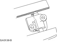
CAUTION:Make sure vise jaw protectors are used. Loosely mount the left-hand timing chain tensioner in a vise. | | | -
CAUTION:During tensioner compression, do not release the ratchet stem until the tensioner piston is fully retracted into its bore or damage to the ratchet stem will result. Using a suitable pin, release the the left-hand timing chain tensioner piston. | | | -
NOTE:The piston should retract with minimal force. If binding occurs, reposition the tensioner in the vise to eliminate side loading. Slowly compress the left-hand timing chain tensioner, by tightening the vise. | | | -
NOTE:The retaining wire or paper clip must remain in position until the timing chain tensioner has been installed. Using suitable 1.5 mm diameter wire or a paper clip, lock the left-hand timing chain tensioner piston in position. | | | -
If the timing marks on the timing chain are not evident, use a permanent marker to mark the crankshaft and camshaft timing marks on the left-hand timing chain. - Mark any link to use as the crankshaft timing mark.
- Count 29 links from the crankshaft timing mark and mark this link as the exhaust camshaft sprocket timing mark.
- Continue counting to link 42. Mark this link as the intake camshaft sprocket timing mark.
| | | -
NOTE:Install the crankshaft sprockets with the timing marks facing outwards. NOTE:Align the marks on the timing chain with the marks on the camshaft and crankshaft sprockets. Install the left-hand timing chain. - Install the left-hand timing chain guide.
- Install the crankshaft sprockets.
- Install the left-hand timing chain.
| | | -
Install the left-hand timing chain tensioner. - Install the left-hand timing chain tensioner arm.
- Position the timing chain tensioner.
- Install the bolts.
| | | -
Remove the left-hand timing chain tensioner piston retaining wire. | | | -
NOTE:Lubricate the valve tappets with clean engine oil before installation. Install the right-hand cylinder head valve tappets. | | | -
CAUTION:The cam followers must be installed in their original position. NOTE:Lubricate the cam followers with clean engine oil before installation. Install the right-hand cylinder head cam followers. | | | -
NOTE:Lubricate the camshafts with clean engine oil before installation. Install the right-hand camshafts. | | | -
Position the right-hand camshafts as shown. - The mark on the exhaust camshaft at the 12 o'clock position.
- The mark on the intake camshaft at the 3 o'clock position.
| | | -
CAUTION:The camshaft journal caps must be installed in their original position. CAUTION:Do not install the camshaft journal thrust caps until all the camshaft bearing caps have been installed, or damage to the thrust caps may occur. NOTE:Lubricate the camshaft journal caps with clean engine oil before installation. Install the right-hand camshaft journal caps. - Tighten the bolts in the sequence shown in several stages.
| | | -
Install the crankshaft pulley retaining bolt and washer. - Rotate the crankshaft in a clockwise direction to position the keyway at the 3 o'clock position.
| | | -
Remove the crankshaft pulley retaining bolt and washer. | | | -
CAUTION:Make sure vise jaw protectors are used. Loosely mount the right-hand timing chain tensioner in a vise. | | | -
CAUTION:During tensioner compression, do not release the ratchet stem until the tensioner piston is fully retracted into its bore or damage to the ratchet stem will result. Using a suitable pin, release the the right-hand timing chain tensioner piston. | | | -
NOTE:The piston should retract with minimal force. If binding occurs, reposition the tensioner in the vise to eliminate side loading. Slowly compress the right-hand timing chain tensioner, by tightening the vise. | | | -
NOTE:The retaining wire or paper clip must remain in position until the timing chain tensioner has been installed. Using suitable 1.5 mm diameter wire or a paper clip, lock the left-hand timing chain tensioner piston in position. | | | -
If the timing marks on the timing chain are not evident, use a permanent marker to mark the crankshaft and camshaft timing marks on the right-hand timing chain. - Mark any link to use as the crankshaft timing mark.
- Count 29 links from the crankshaft timing mark and mark this link as the exhaust camshaft sprocket timing mark.
- Continue counting to link 42. Mark this link as the intake camshaft sprocket timing mark.
| | | -
NOTE:Align the marks on the timing chain with the marks on the camshaft and crankshaft sprockets. Install the right-hand timing chain. - Install the right-hand timing chain guide.
- Install the right-hand timing chain.
| | | -
Install the right-hand timing chain tensioner. - Install the right-hand timing chain tensioner arm.
- Position the timing chain tensioner.
- Install the bolts.
| | | -
Remove the right-hand timing chain tensioner piston retaining wire. | | | -
Install the crankshaft pulley retaining bolt and washer. | | | -
NOTE:Ignore the timing flags on the rear of the camshaft sprockets. NOTE:Check the number of timing chain links between the camshaft front timing marks and between the camshaft front timing marks and timing marks on the crankshaft sprockets. Rotate the crankshaft approximately 120 degrees in a counterclockwise direction and check the timing. - There should be 12 chain links between the camshaft timing marks.
- There should be 27 chain links between the camshaft and crankshaft timing marks.
- There should be 30 chain links between the camshaft and crankshaft timing marks.
| | | -
Remove the crankshaft pulley retaining bolt and washer. | | | -
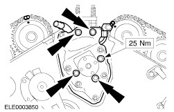
CAUTION:The pulse wheel has two keyway slots and is used in several different engines. Install the pulse wheel in the keyway slot stamped 25, color coded blue. | | | -
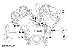
NOTE:Install the engine front cover within six minutes of applying the sealant. Apply a 6 mm dot of sealant to the mating faces in the positions shown. | | | -
NOTE:Install new engine front cover gaskets. Install the engine front cover. - Tighten the studs in the sequence shown.
| | | -
NOTE:Tightening sequence. Tighten the remaining engine front cover bolts and studs. | | | -
NOTE:Coat the new O-rings with engine oil. Install the sensors and wiring brackets. - CKP sensor.
- CMP sensor.
- Wiring bracket.
- Wiring bracket.
| | | -
NOTE:Install a new crankshaft front seal. Using the special tool, install the crankshaft front seal. - Lubricate the outer ring and the sealing lip of the seal with engine oil.
- Draw in the crankshaft front seal using the special tool and the washer of the crankshaft pulley/vibration damper bolt.
| | | -
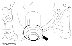
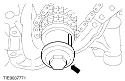
Using the special tool, install the crankshaft pulley/vibration damper. | | | -
Remove the special tool and the crankshaft pulley retaining washer. | | | -
NOTE:Tightening sequence. Using the special tool, install the crankshaft pulley/vibration damper. - Seal off the Woodruff key in the crankshaft pulley/vibration damper with silicone sealer and sealant.
- Tighten the bolt in four stages.
- Stage 2: Turn the bolt back a full turn.
| | | -
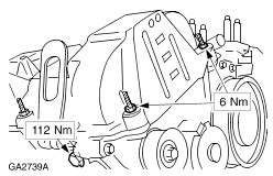
NOTE:Do not tighten the power steering pump bracket retaining bolts and nuts at this stage. Install the power steering pump and bracket. | | | -
NOTE:The longer 84 mm retaining bolts should be tightened first. Tighten the 84 mm power steering pump retaining bolts. | | | -
Tighten the power steering pump retaining nuts. | | | -
NOTE:The indentation on the pulley must face towards the front of the engine. Install the pulley to the power steering pump. | | | -
Install the camshaft seal carrier. | | | -
CAUTION:Do not damage the running surface of the camshaft. Using the special tools, install the camshaft seal. - Lubricate the outside of the seal with engine oil.
| | | -
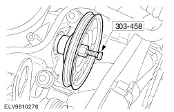
Using the special tool, install the camshaft pulley. - Heat the belt pulley, locate it in position and draw it on as far as it will go.
| | | -
Using the special tool, install the left-hand spark plugs. | | | -
Using the special tool, install the right-hand spark plugs. | | | -
NOTE:Clean the mating faces with metal surface cleaner. Apply sealant to the mating faces of the cylinder head in the positions shown. | | | -
NOTE:Install new valve cover gaskets. Install the valve covers. | | | -
Install the wiring harness retaining plate and the right-hand engine lifting eye. | | | -
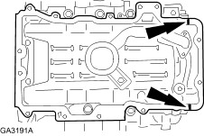
NOTE:Install the oil pan within six minutes of applying the sealant. Apply a 10 mm bead of sealant to the cylinder block in the positions shown. | | | -
NOTE:Location of the studs. NOTE:Tightening sequence. NOTE:Install the oil pan within six minutes of applying the sealant. Install the oil pan with a new gasket. | | | -
Install the oil pan heat shields. | | | -
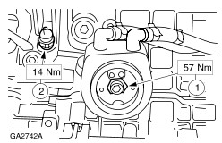
Install the oil cooler and the oil pressure switch. - Install the oil cooler retaining bolt.
- Apply sealer to the thread of the oil pressure switch and install the switch.
- Coat the oil cooler seal, the O-ring and the oil filter seal with engine oil.
| | | -
NOTE:Install a new left-hand exhaust manifold gasket. NOTE:Tightening sequence. Install the left-hand exhaust manifold. | | | -
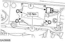
Install the generator bracket. | | | -
Install the generator. - Generator bolts.
- Bracket bolt.
| | | -
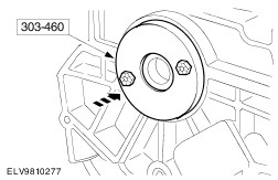
Using the special tool, install the crankshaft rear seal. - Lubricate the outer ring and sealing lip with engine oil.
| Vehicles with manual transaxle | | -
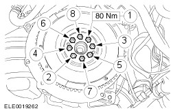
Install the flywheel. - Install the adapter plate.
- Apply sealer to the bolts and tighten them working diagonally.
- Using the special tool 205-072, hold the crankshaft by the vibration damper.
| Vehicles with automatic transaxle | | -
NOTE:Tightening sequence. Install the adapter plate and the flexplate. | All vehicles | | -
Install the coolant pump. - Tighten the new bolts in two stages.
- Connect the coolant hose.
- Connect the coolant hose.
| | | -
Install the coolant connecting pipe between the cylinder heads. | | | -
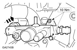
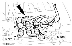
Install the positive crankcase ventilation (PCV) valve and hose. - Attach the PCV valve and hose.
- Tighten the nut.
| | | -
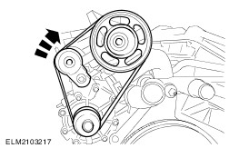
Install the water pump drive belt. - Rotate the belt tensioner clockwise to release the tension on the drive belt.
| | | -
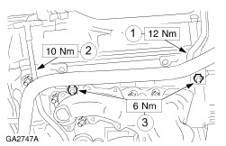
Attach the coolant distribution pipe, the engine lifting eye and the oil dipstick. - Install the engine lifting eye.
- Install the dipstick with a new oiled O-ring.
- Screw on the nuts.
| | | -
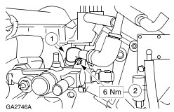
Using the special tool, install the thermostat housing with the coolant hoses. | | | -
NOTE:Install new gaskets with the locating lugs facing downwards. NOTE:Tightening sequence. Install the lower intake manifold. | | | -
Install the fuel injection system wiring harness. - ECT sensor plug.
- DPFE sensor plug.
- Fuel injector connector.
| | | -
Connect the plugs. - Oil pressure switch.
- CKP sensor.
- CMP sensor.
- Clip the wiring harness in place.
| | | -
NOTE:Install new gaskets with the locating lugs pointing downwards. NOTE:Tightening sequence. Install the upper intake manifold. | | | -
Connect the hoses and plugs - Plug to the TP sensor.
- Positive crankcase ventilation hose.
- Plug to the IAC valve.
| | | -
Connect the vacuum hoses. - To the upper part of the intake manifold.
- To the electronic vacuum regulator.
- To the fuel pressure regulator.
- To the DPFE.
- To the EGR valve.
| | | -
Install the electronic ignition (EI) coil. - Connect the electrical connectors.
| | | -
Install the IMRC actuator. - Install the retaining bolts.
- Connect the IMRC electrical connector.
| | | -
Install the wiring harness and connect the electrical conectors. - Attach the wiring rail.
- Generator cable.
- DPFE sensor plug.
- Electronic vacuum regulator plug.
- ECT sensor to coolant connection pipe.
| | | -
Remove the special tools. | | | -
Install the intermediate driveshaft bracket. | | | -
NOTE:Install a new right-hand exhaust manifold gasket. NOTE:Tightening sequence. Install the right-hand exhaust manifold. | | | -
Connect the EGR pipe to the EGR valve. - Screw on the EGR pipe.
- Connect the hoses to the EGR pipe.
| Vehicles with manual transaxle | | -
Install the clutch disc and pressure plate. For additional information, refer to Section 308-01 Clutch. | |