| Installation Special Tool(s) | | Engine support bar 303-290 (21-140) | | | Adapter for 303-290 303-290-01 (21-140-01) | | | Adapter for 303-290 303-290-02 (21-140-02) | | | Adapter for 303-290 303-290-03 (21-140-03) | | | Lifting bracket, engine 303-122 (21-068A) | | | Gauge, engine alignment 502-003 (21-172) | | | Radiator hose clamp remover/installer 303-397 (24-003) | General Equipment Workshop hoist Workshop jack Materials Name Specification Cable ties Rivets 4 mm Installation All Vehicles | | -
General notes. - The position markings for the engine mountings and engine roll restrictors are described looking from the transmission towards the engine.
- Sub-operations for particular variants which do not apply to all vehicles are marked clearly with a note.
- Use Special Tool 303-397 as required when installing coolant and ventilation hoses.
| | | -
Hook the engine and manual transmission assembly into the workshop hoist, move it into installation position and lower it. | | | -
Position a workshop trolley jack underneath the oil pan and unhook the engine and manual transmission from the workshop hoist. | | | -
Attach the engine support, insert the engine and manual transmission assembly and let the support take the weight. | | | -
NOTE:Do not tighten the bolts. Attach the front engine mounting. | | | -
NOTE:Do not tighten the nuts on the transmission. Attach the rear engine mounting. | | | -
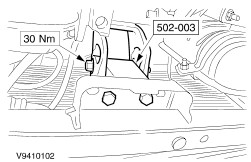
Attach the special tool to the subframe. - Screw the center bolt into the gauge and tighten.
| | | -
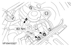
Tighten the front engine mounting bolts. | | | -
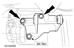
Tighten the rear engine mounting nut. | | | -
Detach the special tools. | | | -
Attach the bracket for the right-hand engine roll restrictor. | | | -
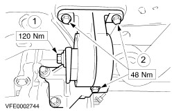
Attach the right-hand engine roll restrictor, in doing so make sure it is centered. - Tighten the center bolt for the engine roll restrictor.
- Tighten the bolts.
| | | -
Attach the left-hand engine roll restrictor. - Remove Special Tool 502-003
- Tighten the center bolt for the engine roll restrictor.
- Tighten the nuts.
| Vehicles with air conditioning | | -
Install the air conditioning compressor. | Vehicles with air conditioning | | -
Attach the heat shield to the air conditioning compressor. | All vehicles | | -
Attach the thermostat housing distribution pipe. | Vehicles with air conditioning | | -
Connect the multiplug for the air conditioning compressor. | All vehicles Vehicles with air conditioning | | -
Attach the air conditioning condenser to the radiator. | | | -
CAUTION:The inner joint must not be bent more than 18 degrees, the outer joint not more than 45 degrees. Install the left-hand front driveshaft. - Pull the spindle carrier outwards and insert the front driveshaft into the transmission.
| | | -
CAUTION:The inner joint must not be bent more than 18 degrees, the outer joint not more than 45 degrees. Install the right-hand front driveshaft. - Pull the spindle carrier outwards and push the front driveshaft onto the intermediate shaft.
| | | -
CAUTION:Do not damage the boot or the toothed sensor wheel of the front ABS sensor. Attach the lower suspension arm on both sides (right-hand side shown). | | | -
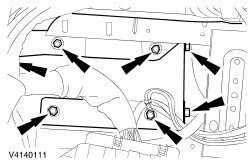
Attach the right-hand lower wheel arch trim panel (shown with the wheel removed). - Tighten the upper wheel arch trim panel.
| | | -
Install the front exhaust pipe and catalytic converter. - Hook the catalytic converter into the rubber loop.
| | | -
Install the front exhaust pipe. | | | -
Attach the gearshift cables to the transmission. - Insert the bracket.
- Screw in the nuts.
- Clip in the gearshift cables.
| | | -
Attach the coolant hose to the radiator. | | | -
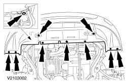
Install the lower radiator cover. - Screw in the coolant drain plug.
| | | -
Attach the engine undershield (if equipped). | | | -
Attach the ground cable to the transmission and connect the main wiring harness connector. | | | -
Connect the plug to the PCM and attach the ground cable to the body. - Hook the engine wiring harness into the bulkhead.
| | | -
NOTE:Use new rivets (4 mm). Rivet the PCM cover in place. | | | -
CAUTION:No hydraulic fluid should come into contact with the drivebelt. Attach the power steering line. - High-pressure line and bracket with ground cable.
- Return line
- Connector
| | | -
Install the power steering fluid reservoir. | | | -
Push on the heater vacuum hoses. | | | -
Attach the fan to the radiator. | | | -
Attach the fan to the radiator. | | | -
Attach the fan motor ground cable to the body. | | | -
Connect the two fan motor plugs. - Clip the plugs and wiring in place.
| Vehicles with air conditioning | | -
Connect the plug to the air conditioning collector/dehydrator. | All vehicles | | -
NOTE:Prevent the piston rod from moving with an Allen key. Tighten the suspension strut nut on the right and left-hand side. | | | -
Attach the coolant hose for the distribution pipe to the thermostat housing. | | | -
Attach/connect the coolant hoses. | | | -
Attach the coolant hose to the top of the radiator. | | | -
Install the coolant expansion tank. - Connect the plug for the coolant level switch (if equipped).
| | | -
Attach the coolant hoses. | | | -
Attach the clutch slave cylinder line to the slave cylinder. | | | -
Connect the positive lead of the starter motor. - Push the positive lead into the wiring casing and close the casing.
| | | -
Connect the starter motor. | | | -
Install the battery console. | | | -
Attach the central junction box (CJB). | | | -
Attach the bracket for the cables. | | | -
Push on the vacuum hose for the evaporative emission system. | | | -
Attach the cruise control cable. | | | -
Attach and adjust the accelerator cable (illustration shows vehicle equipped with traction control system). - Insert the cable into the bracket and push on a plastic clip.
- Hook the spring in place.
- Check whether the throttle valve opens fully when the accelerator pedal is floored and adjust as necessary.
- To adjust, pull off the metal clip, fully depress the accelerator pedal and slide on the metal clip.
| | | -
Install the air cleaner housing. - Two PCV hoses
- Hose clip at the throttle housing
- Idle control valve vacuum hose
- MAF sensor multiplug
- IAT sensor multiplug
- Connect the brake booster vacuum pipe at the top of the intake manifold.
| | | -
Install the upper engine cover. | | | -
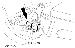
Clip in the gear lever boot. | | | -
Fill up and bleed the power steering system. For additional information, refer to Section 211-02 Power Steering. | | | -
Standard finishing operations. - Pressure-test the cooling system for leaks.
- Check the routing of vacuum hoses and cables and secure as necessary with cable ties.
- Detach the auxiliary tools from the hood and close the hood.
- Reprogram the pre-set radio stations.
- Carry out a road test to enable the PCM to collect data.
- Check fluid levels again and correct if necessary.
| |