| Installation Special Tool(s) | | Engine support bar 303-290 (21-140) | | | Adapter for 303-290 303-290-01 (21-140-01) | | | Adapter for 303-290 303-290-02 (21-140-02) | | | Adapter for 303-290 303-290-03 (21-140-03) | | | Lifting bracket, engine 303-122 (21-068A) | | | Gauge, engine alignment 502-003 (21-172) | | | Radiator hose clamp remover/installer 303-397 (24-003) | General Equipment Workshop hoist Workshop jack Steel rule Materials Name Specification Cable ties Rivets 4 mm Installation All Vehicles | | -
CAUTION:If the installation depth of the torque converter is insufficient it will cause damage to the transmission and drive plate (the torque converter will not engage properly in the oil pump). NOTE:The torque converter must remain at the correct installation depth throughout the whole installation procedure. Make sure the adapter plate is correctly positioned. Put the torque converter in position. - Lay a steel straightedge across the transmission flange.
- Measure the installation depth of the torque converter.
| | | -
Hook the engine into the workshop hoist, move it into installation position and lower it. | | | -
Position a workshop trolley jack underneath the oil pan and unhook the engine from the workshop hoist. | | | -
Attach the engine support, insert the engine and let the support take the weight. | | | -
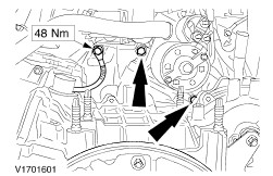
Attach the drive belt tensioner (shown with the front engine mounting bracket installed). | | | -
NOTE:Do not tighten the bolts. Attach the front engine mounting. | | | -
NOTE:Do not tighten the nuts. Install the front engine mounting bracket. | | | -
Install the starter motor. | | | -
Screw in the upper flange bolts. | | | -
Tighten the flange bolts on the left-hand side of the transmission. | | | -
Tighten the lower flange bolts. | | | -
Attach the torque converter to the engine drive plate (4 nuts). - Install the plastic cover.
| | | -
Undo the left-hand engine roll restrictor. | | | -
Unscrew the center bolt from the right-hand engine roll restrictor. | | | -
Loosen the bolts on the bracket for the right-hand engine roll restrictor. | | | -
Attach the special tool to the subframe. - Screw the center bolt into the special tool and tighten it.
| | | -
Tighten the front engine mounting bolts. | | | -
Tighten the nuts and bolts on the front engine mounting bracket. | | | -
Detach the special tools. | | | -
Attach the ignition cable bracket to the front engine mounting bracket. | | | -
Attach the right-hand engine roll restrictor. - Tighten the center bolt on the engine roll restrictor.
- Tighten the bolts.
| | | -
Attach the left-hand engine roll restrictor. - Remove Special Tool 502-003
- Tighten the center bolt on the engine roll restrictor.
- Tighten the nuts.
| Vehicles with air conditioning | | -
Install the air conditioning compressor. | | | -
Attach the air conditioning compressor heat shield. | All vehicles | | -
Attach the thermostat housing distribution pipe. | Vehicles with air conditioning | | -
Connect the multiplug for the air conditioning compressor. | All vehicles Vehicles with air conditioning | | -
Attach the air conditioning condenser to the radiator. | All vehicles | | -
Install the intermediate shaft. - Insert the intermediate shaft in the transmission.
| | | -
CAUTION:The inner joint must not be bent more than 18 degrees, the outer joint not more than 45 degrees. Attach the heat shield to the center bearing bracket and the front driveshaft to the intermediate shaft. - Attach the heat shield and tighten the nuts.
- Pull the spindle carrier outwards and push the front driveshaft onto the intermediate shaft.
| | | -
CAUTION:Do not damage the boot or the toothed sensor wheel of the front ABS sensor. Attach the right-hand lower suspension arm. | | | -
Connect the VSS multiplug. | | | -
Attach the right-hand lower wheel arch trim panel. | | | -
Install the front exhaust pipe and catalytic converter. - Hook the catalytic converter into the rubber loop.
| | | -
Install the front exhaust pipe. | | | -
Attach the lower oil cooler line. | | | -
Attach the coolant hose to the radiator. | | | -
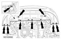
Install the lower radiator cover. - Screw in the coolant drain plug.
| | | -
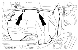
Attach the engine undershield (if equipped). | | | -
Attach the upper oil cooler line. | | | -
Connect the main wiring harness connector. - Join the connector.
- Tighten the bolt.
| | | -
Connect the plug to the PCM and attach the ground cable to the body. - Hook the engine wiring harness into the bulkhead.
| | | -
NOTE:Use new rivets (4 mm). Rivet the PCM cover in place. | | | -
CAUTION:No hydraulic fluid should come into contact with the drivebelt. Attach the power steering line. - Power steering high-pressure line and bracket with ground cable.
- Power steering return line.
- Connect the plug.
| | | -
Install the power steering fluid reservoir. | | | -
Push on the heater vacuum hoses. | | | -
Attach the fan to the radiator. | | | -
Attach the fan to the radiator. | | | -
Attach the fan motor ground cable to the body. | | | -
Connect the two fan motor plugs. - Clip the plugs and wiring in place.
| Vehicles with air conditioning | | -
Connect the plug to the air conditioning collector/dehydrator. | All vehicles | | -
NOTE:Prevent the piston rod from moving with an Allen key. Tighten the suspension strut nut on the right and left-hand side. | | | -
Connect the plugs to the transmission (shown on an automatic transmission removed from the vehicle). - TSS sensor plug.
- Automatic transmission control plug
- Coolant temperature sender unit
- TR switch plug
- Clip the wiring harness in place.
| | | -
Connect the positive lead of the starter motor. - Push the positive lead into the wiring casing and close the casing.
| | | -
Connect the starter motor. | | | -
Attach the gearshift cable. - Press the gearshift cable into the selector lever and clip it in.
- Install the gearshift cable bracket.
| | | -
Attach the coolant hose for the distribution pipe to the thermostat housing. | | | -
Attach/connect the coolant hoses. | | | -
Install the coolant hose at the top of the radiator. | | | -
Install the coolant expansion tank. - Connect the plug for the coolant level switch (if equipped).
| | | -
Attach the coolant hoses. | | | -
Attach the bracket for the cables. | | | -
Push on the vacuum hose for the evaporative emission system. | | | -
Attach the cruise control cable. | | | -
Attach and adjust the accelerator cable (illustration shows vehicle equipped with traction control system). - Insert the cable into the bracket and push on a plastic clip.
- Hook the spring in place.
- Check whether the throttle valve opens fully when the accelerator pedal is floored and adjust as necessary.
- To adjust, pull off the metal clip, fully depress the accelerator pedal and slide on the metal clip.
| | | -
Install the air cleaner housing. - Two PCV hoses
- Hose clip at the throttle housing
- Idle control valve vacuum hose
- MAF sensor multiplug
- IAT sensor multiplug
- Connect the brake booster vacuum pipe at the top of the intake manifold.
| | | -
Install the upper engine cover. | | | -
Fill up and bleed the power steering system. For additional information, refer to Section 211-02 Power Steering. | | | -
Standard finishing operations - Close the coolant expansion tank.
- Check the fluid levels and correct as necessary.
- Pressure-test the cooling system for leaks.
- Check the routing of vacuum hoses and cables and secure as necessary with cable ties.
- Insert the engine oil dipstick.
- Detach the auxiliary tools from the hood and close the hood.
- Reprogram the pre-set radio stations.
- Carry out a road test to enable the PCM to collect data.
- Check fluid levels again and correct if necessary.
| |