| Installation Special Tool(s) | | Lifting bracket, engine 21-068A | | | Remover and installer, radiator hose clip 24-003 | General Equipment Workshop hoist Drill 4mm drill bit Materials Name Specification Cable ties Installation All vehicles | | -
General notes. - The positions of the engine mountings and engine roll restrictors are described looking from the transmission towards the engine.
- Any steps which only apply to certain variants and not to all vehicles are clearly indicated.
- Use Special Tool 24-003 as required when connecting coolant or ventilation hoses.
| | | -
Hook the engine into the workshop hoist, move it into installation position and lower it. | | | -
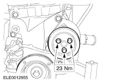
Install the drive belt idler pulley. | | | -
Loosely screw in the upper flange bolts. | | | -
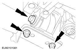
Install the rear engine mounting. - Three nuts
- Three bolts
| | | -
Position the trolley jack under the sump and unhook the engine from the workshop hoist. | | | -
Install the front engine mounting. | | | -
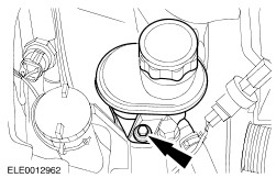
Move the power steering pump into installation position and attach the power steering reservoir. | | | -
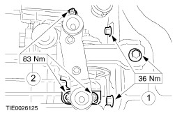
Screw in the flange bolts on the right-hand side of the transmission. | | | -
Screw in the flange bolts on the left-hand side of the transmission. | | | -
Remove the left-hand engine roll restrictor. | | | -
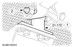
Align the engine/transmission assembly. - Attach the special tool in place of the left-hand engine roll restrictor.
- Fit the bolt and tighten it slightly.
| | | -
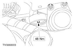
Tighten the rear engine mounting nuts. | | | -
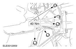
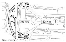
Install the front engine mounting bracket on the engine mounting. - Tighten the four nuts on the engine.
- Tighten the nut on the engine mounting.
| | | -
Screw in the center bolt on the right-hand engine roll restrictor. | Vehicles with air conditioning | | -
Install the air conditioning compressor. - Connect the plug for the magnetic clutch.
| All vehicles | | -
Attach the coolant hoses and the bracket for the coolant line. - Attach the coolant hose to the radiator.
- Attach the coolant pipe bracket to the oil pan.
| | | -
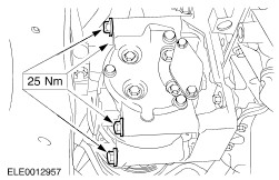
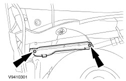
Attach the center bearing bracket to the engine. | | | -
Attach the heat shield to the center bearing bracket and the right-hand front axle driveshaft to the intermediate shaft. | | | -
CAUTION:Do not damage the gaiter or the ABS front sensor toothed ring. Attach the right-hand lower suspension arm. | | | -
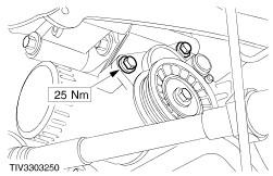
Attach the coolant pump pulley. | | | -
NOTE:Immobilize the crankshaft. Using a screwdriver, lock the flywheel at the ring gear (hole in transmission housing). Attach the crankshaft pulley/vibration damper. | | | -
Install the drive belt tensioner. | | | -
Install and tension the drive belt. | | | -
Attach the right-hand lower wheel arch trim panel. - Undo one bolt of the upper wheelhouse cover.
| | | -
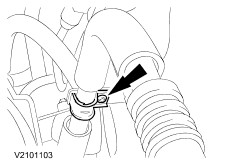
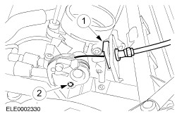
Attach the brake booster vacuum line to the intake manifold. - Insert the vacuum line into the quick-release coupling and let it snap in place.
| | | -
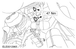
Screw in the lower bolts on the power steering pump. | | | -
Screw in the lower bolt on the starter motor and insert the starter motor. | | | -
Connect the starter motor. | | | -
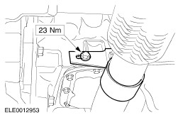
Attach the exhaust pipe bracket to the cylinder block. | | | -
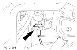
Connect the connector for the vehicle speed sensor (VSS). | | | -
Connect the plug for the heated oxygen sensor (HO2S). | | | -
Attach the coolant hose to the coolant pump and to the coolant line. | | | -
Screw in the upper bolts on the power steering pump. | | | -
NOTE:Stop the piston rod from turning using an Allen key. Tighten the right-hand suspension strut nut. | | | -
Install the catalytic converter on the exhaust manifold. | | | -
Install the heat shield. - Install the lower bolts.
- Insert the oil dipstick.
- Screw in the upper bolts.
- Attach the coolant hose to the bracket.
| | | -
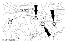
NOTE:Attach the ground cable and the cable holder. Tighten the upper flange bolts. | | | -
Install the upper starter motor bolts. | Vehicles with air conditioning | | -
Attach the bracket to the air conditioning line. | All vehicles | | -
Install the coolant expansion tank. | | | -
Connect the coolant hoses to the thermostat housing. | | | -
Connect the plug and wiring to the alternator. | | | -
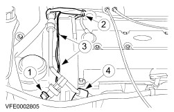
Connect the plug and attach the ground cable and the bracket for the high-pressure line. - Connect the plug to the power steering pressure (PSP) switch.
- Attach the ground cable and the bracket for the power steering high-pressure line to the engine lifting eye.
- Clip the HO2S cable in place.
- Attach the bracket to the power steering high-pressure line.
| | | -
Attach the engine wiring harness. - Connect the PCM connector.
- Install the bolt.
- Attach the ground cable.
| | | -
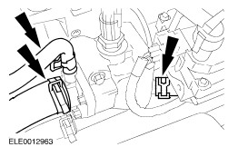
Connect the plug. - Connect the engine wiring harness connector and screw in the bolt.
- Connect the transmission control plug.
| | | -
Connect the plug to the coolant temperature sensor. | | | -
Connect the plugs for the ignition coil. | | | -
Push on the vacuum hoses for the EGR system. | | | -
Connect the vacuum hoses to the intake manifold. | | | -
Attach the accelerator cable. - Attach the plastic clip.
- Hook the cable in place.
| | | -
Install the air cleaner housing. - Insert the air cleaner housing into the rubber bushings.
- Attach the positive crankcase ventilation (PCV) hose.
- Connect the intake hose.
| | | -
Attach the intake pipe. - Connect the mass air flow (MAF) plug.
- Connect the plug to the intake air temperature (IAT) sensor.
- Screw in one bolt and attach two nuts.
| | | -
Top up and bleed the power steering system. For additional information, refer to Section 211-02 Power Steering. | | | -
Standard finishing operations. - Connect the battery ground lead.
- Close the coolant recovery tank.
- Check the fluid levels and correct as necessary.
- Check the routing of the vacuum hoses and cables and secure them with cable ties if necessary.
- Detach the auxiliary tool from the hood.
- Reprogram the pre-set radio stations.
- Carry out a road test to enable the PCM to collect data.
| |