| Installation Special Tool(s) | | Socket wrench, steering gear 211-186/202 (13-013) | | | Subframe locating pins 205-316 (15-097A) | | | Engine support bar 303-290 (21-140) | | | Adapter for 303-290 303-290-01 (21-140-01) | | | Adapter for 303-290k 303-290-02 (21-140-02) | | | Adapter for 303-290 303-290-03 (21-140-03) | | | Wrench, Intake Manifold 303-120 (21-066) | | | Alignment gauge, for powertrain 502-003 (21-172) | General Equipment Transmission jack Retaining strap Steel straightedge Materials Name Specification High-temperature grease ESD-M1C220-A Automatic transmission fluid ESP-M2C166-H Installation All Vehicles | | -
General note. - The torque converter hub must be engaged fully in the oil pump drive gear.
- The locations of engine and transaxle mountings and engine support insulators are described looking from the transaxle to the engine.
- All self-locking nuts must be renewed.
| | | -
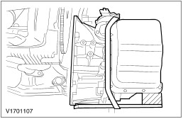
CAUTION:The torque converter must remain at the correct installation depth throughout the whole installation procedure. NOTE:The torque converter studs must be aligned with the engine drive plate holes before any transaxle retaining bolts are installed. Install the torque converter. | | | -
CAUTION:The torque converter hub must be engaged fully in the oil pump drive gear. Check the installation depth of the torque converter. - Lay a steel straightedge agross the automatic transaxle flange.
- Check the installation depth between the transaxle flange and the torque converter centering spigot for the correct clearance.
- Apply a thin layer of high-temperature grease to the centering spigot bore on the torque converter.
| | | -
CAUTION:The torque converter must remain at the correct installation depth throughout the entire installation procedure. Check that the adapter plate is in the correct position. - Make sure the studs on the torque converter are entered into the engine drive plate and loosely install in the transaxle retaining flange bolts.
| | | -
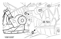
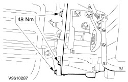
Tighten the transaxle left-hand retaining bolts. | | | -
Tighten the transaxle right-hand retaining bolts. | | | -
NOTE:Install new torque converter retaining nuts. Attach the torque converter to the engine drive plate (four nuts). - Install the rubber cover.
| | | -
Attach the vent pipe to the automatic transmission oil pan (if equipped). | | | -
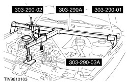
Lift the engine and automatic transmission to installation height using the engine support bar. | | | -
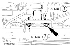
Loosen the center bolt on the rear engine mounting and align the rear engine mounting bracket without placing it under stress. | | | -
NOTE:Do not tighten the nuts at this stage. Install the rear engine mounting. | | | -
CAUTION:Use an open ended spanner on the fluid line adapter to prevent it from turning. Attach the transaxle oil cooler line to the transaxle. | | | -
Connect the turbine shaft speed (TSS) sensor electrical connector and clip the wiring harness in place. | | | -
CAUTION:Use an open ended spanner on the fluid line adapter to prevent it from turning. Attach the transaxle oil cooler line to the transaxle. | | | -
Connect the vehicle speed sensor (VSS) electrical connector (if equipped). | | | -
Detach the left-hand engine roll restrictor from the subframe. | | | -
NOTE:The gauge is marked with an arrow and "Front". Attach the gauge to the subframe. - Attach the special tool.
- Install the bolts.
- Install the center bolt.
| | | -
NOTE:Do not tighten the center bolt. Install the center bolt. | | | -
Insert the two rubber guides of the lower radiator spigots into the subframe. | | | -
NOTE:Do not tighten the bolts. NOTE:Align the steering gear and the fluid line bracket. NOTE:Place a suitable piece of wood underneath the subframe. Lift the subframe into installation position using the transmission jack and attach it at the front. - Secure the radiator in the subframe (push fit)
| | | -
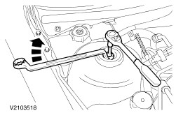
Using the special tool and install the steering gear (two bolts). | | | -
NOTE:Attach the bracket for the power steering fluid line and the bracket for the coolant line to the subframe. Using the special tool and install the steering gear heat shield. | | | -
Align and attach the subframe. - Insert the guide pins.
NOTE:The subframe must not move when the bolts are tightened. -
- Tighten the bolts working diagonally.
| | | -
Attach the gauge to the automatic transmission bracket. - Tighten the center screw.
| | | -
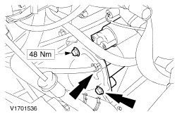
CAUTION:Do not twist or strain the rear engine mounting. Tighten the nuts and the center bolt on the rear engine mounting bracket. | | | -
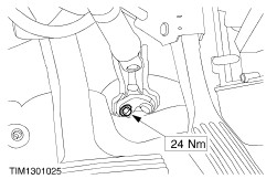
NOTE:Center the engine roll restrictor. Tighten the center bolt on the right-hand engine roll restrictor. | | | -
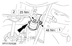
Install the left-hand engine roll restrictor. - Tighten the center bolt.
- Tighten the nuts.
| | | -
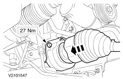
CAUTION:Support the halfshaft. The inner joint must not be bent more than 18 degrees, the outer joint must not be bent more than 45 degrees. CAUTION:Do not damage the halfshaft oil seal. CAUTION:Make sure the snap ring is correctly seated. CAUTION:Make sure that the snap ring is fully engaged. Install the left-hand front driveshaft using a new snap-ring. - Remove the installation sleeve.
| | | -
CAUTION:Support the halfshaft. The inner joint must not be bent more than 18 degrees, the outer joint must not be bent more than 45 degrees. CAUTION:Do not damage the halfshaft oil seal. CAUTION:Make sure that the snap ring is fully engaged. Attach the right-hand halfshaft and the intermediate shaft to the transaxle. - Attach the intermediate shaft bearing to the carrier.
| | | -
CAUTION:Protect the ball joint using a soft cloth to prevent damage. CAUTION:Do not damage the ABS sensor ring. Attach the lower suspension arms and stabilizer link rods. | Vehicles with air conditioning | | -
Attach the air conditioning dehydrator to the subframe. | All vehicles | | -
Install the right-hand vibration damper. - Install the vibration damper
- Install the vibration damper bracket
| | | -
Attach the power steering fluid lines bracket to the subframe. | | | -
Attach the transaxle fluid line to the bracket. | | | -
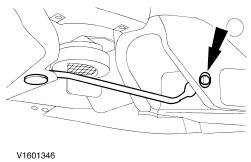
Attach the struts to the subframe. | | | -
Install the lower wheelhouse covers. | | | -
CAUTION:Overstretching the flexible pipe can cause damage. Attach the exhaust pipe with a new gasket and hook it into the rubber loops. | | | -
Attach the steering shaft to the steeering linkage. | | | -
Remove the special tools. | | | -
Pre-tighten the nuts on both suspension struts. - Stop the assembly from turning
| | | -
Tighten the nuts on both suspension struts to torque. | | | -
NOTE:Ground lead bracket. Screw in the flange bolts. | | | -
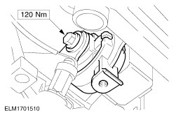
Attach the starter motor to the transaxle. | | | -
Install the selector lever cable. - Attach the selector lever cable to the selector lever.
- Attach the selector lever cable bracket to the transaxle.
| | | -
Remove the rear exhaust system heat shield. | | | -
NOTE:The selector lever has its own engagement system. Set the selector lever on the automatic transmission to the "D" (drive) position and check the adjustment of the selector lever cable. - Hold the adjustment mechanism to stop it from moving.
- Undo the latch on the selector lever cable.
- The markings on the selector lever must line up.
| | | -
Lock the selector lever cable. - Hold the adjustment mechanism to stop it from moving.
- Close the latch on the selector lever cable.
| | | -
Install the rear exhaust system heat shield. | | | -
Install the lower radiator cover. | | | -
Connect the OSS sensor electrical connector (if equipped). | | | -
Install the engine undershield (nine bolts). | | | -
Connect the transaxle electrical connectors. - Attach the ground cable to the transaxle case.
- Connect the automatic transaxle electrical connector.
- Connect the transmission range (TR) sensor electrical connector.
- Install the wiring harness retaining clip
| | | -
Remove the pins from the radiator support. | | | -
Install the intake pipe and the air filter housing. - Install the positive crankcase ventilation (PCV) hose.
- Install the intake hose.
- Press the air cleaner housing into the rubber bushing.
| | | -
Install the intake pipe and the air intake housing. - Connect the mass air flow (MAF) sensor electrical connector.
- Connect the intake air temperature (IAT) sensor electrical connector.
- Install the bolt and nuts.
| | | -
Check the transaxle fluid. For additional information, refer to Fluid Level Check in this section. | |