| Disassembly and Assembly of Subassemblies Special Tool(s) | | Remover, taper roller bearing (basic tool) 205-295 (15050A) | | | Collet for 205-295 308-197 (16062) | Materials Name Specification Transmission fluid WSD-M2C200-C Disassembly | | -
CAUTION:The inner synchronizer ring and the synchronizer cone must be handled very carefully. General note | | | -
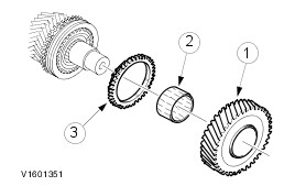
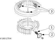
NOTE:The taper roller bearing and the reverse gear wheel can also be pressed off together. Pull off the taper roller bearing on the transmission housing side. | | | -
Remove the reverse gear wheel. - Reverse gear wheel
- Needle roller bearing
- Synchronizer ring.
| | | -
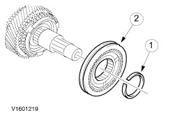
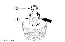
NOTE:If gear changes are difficult, carefully prise off the synchronizer assembly with the 5th gear wheel. Remove the complete 5th/reverse gear synchronizer assembly. - Snap-ring
- Synchronizer assembly, complete
| | | -
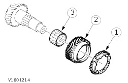
Remove the 5th gear wheel with the synchronizer ring and needle roller bearing. - Synchronizer ring.
- Gear wheel (5th gear)
- Needle roller bearing.
| | | -
Pull off the taper roller bearing on the clutch side. | | | -
CAUTION:The output shaft and output pinion are paired and must only be renewed together. Remove the output pinion and 1st gear wheel. - Remove the snap-ring.
- Press off the output pinion and 1st gear wheel together.
| | | -
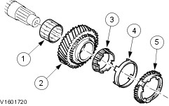
Detach the double synchronizer together with the needle roller bearing. - Needle roller bearing
- Inner synchronizer ring
- Synchronizer cone
- Outer synchronizer ring
| | | -
NOTE:If gear changes are difficult, carefully prise off the synchronizer assembly with the 5th gear wheel. Remove the 1st/2nd gear synchronizer assembly. - Snap-ring
- Synchronizer assembly, complete
| | | -
Remove the double synchronizer together with the 2nd gear wheel. - Outer synchronizer ring
- Synchronizer cone
- Inner synchronizer ring
- Gear wheel (2nd gear)
- Needle roller bearing
| | | -
CAUTION:Carefully pull the selector ring off the synchronizer hub. The detent balls are spring loaded. NOTE:Mark the location of the selector ring. Dismantle the synchronizer assembly. - Pull off the selector ring.
- Synchronizer hub
- Compression spring
- Blocker bar
- Detent ball
| Assembly | | -
NOTE:Do not oil taper roller bearings which are to be used again. Install new taper roller bearings untreated. | | | -
CAUTION:Immerse the double synchronizers in transmission fluid prior to installation. Attach the 2nd gear wheel with double synchronizer and needle roller bearing. - Needle roller bearing
- Gear wheel (2nd gear)
- Inner synchronizer ring
- Synchronizer cone
- Outer synchronizer ring
| | | -
Assemble the 1st/2nd gear synchronizer. - Insert the compression springs.
- Insert the locker bar with the detent balls against the force of the spring.
- Fit the selector ring the right way round and slide it on.
| | | -
NOTE:Attach the synchronizer hub with the small collar and the annular groove facing outwards. Installation position of 1st/2nd gear synchronizer assembly | | | -
NOTE:Attach the synchronizer hub with the small collar and the annular groove facing outwards. Fit the complete 1st/2nd gear synchronizer assembly. - Synchronizer assembly.
- Fit a new snap-ring.
| | | -
Attach the 1st gear wheel with the double synchronizer. - Outer synchronizer ring
- Synchronizer cone
- Inner synchronizer ring
- Gear wheel (1st gear)
- Needle roller bearing
| | | -
CAUTION:There is only one way to fit the output pinion onto the teeth. Press the output pinion on. - Install the output pinion with the mark pointing upwards.
- Press on the output pinion using a suitable length of tube and a press .
- Fit a new snap-ring.
| | | -
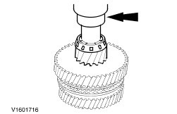
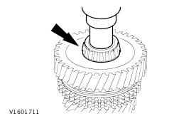
Press the taper roller bearing on at the clutch end. - Press on the taper roller bearing using a suitable length of tube and a press .
| | | -
Attach the 5th gear wheel with synchronizer ring and needle roller bearing. - Needle roller bearing
- Gear wheel (5th gear)
- Synchronizer ring.
| | | -
Assemble the 5th/reverse gear synchronizer. - Insert the compression springs.
- Insert the locker bar with the detent balls against the force of the spring.
- Fit the selector ring the right way round and slide it on.
| | | -
NOTE:Fit the synchronizer hub with the small collar and the ring groove facing outwards. Installation position of 5th/reverse gear synchronizer assembly | | | -
NOTE:Fit the synchronizer hub with the small collar and the ring groove facing outwards. Attach the 5th/reverse gear synchronizer assembly as a unit. - Synchronizer assembly.
- Fit a new snap-ring.
| | | -
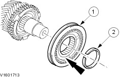
Attach the reverse gear wheel. - Synchronizer ring.
- Needle roller bearing.
- Reverse gear wheel
| | | -
Press on the taper roller bearing on the transmission housing side. - Press on the taper roller bearing using a suitable length of tube and a press .
| |