| Diagnosis and Testing Refer to Wiring Diagrams Section 418-00, for schematic and connector information. Special Tool(s) | | 73 Digital Multimeter or equivalent of 105-R0051 | | | Terminal probe kit 29-011A | Inspection and Verification - In the event of a customer concern, verify whether the fault still arises or whether it relates to an operating error.
- Carry out a visual check for electrical damage to the system components, using the following table:
Visual Inspection Chart | Electrical | - Module(s)
- Wiring looms
- Loose or oxidised connectors
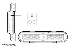
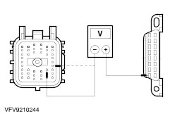
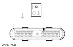
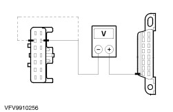
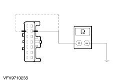
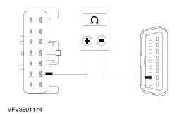
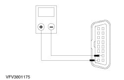
| - If the diagnostic tester shows that it cannot communicate with one or more of the modules, continuity tests can be performed using the tester or an ohmmeter according to the following symptom chart. If one or more diagnostic links is shorted to ground or to battery voltage, then the source of the fault must be located using a volt and ohmmeter according to the following symptom chart.
- If the diagnostic tester cannot communicate with one of the modules you should check the communications to a different module to exclude an incorrect fault diagnosis.
Symptom Chart | Symptom | Possible Sources | Action | | ABS module (Mecatronic 3 with TCS) does not respond to FDS2000 or NGS (or WDS from 97,25 MY) | * ABS (TCS) module * Wiring harness * Poor electrical connections in diagnostic databus ISO 9141 | * GO TO Pinpoint Test A | | ABS module (Mecatronic 3 TCS) does not respond to FDS2000 or NGS (or WDS from 97,25 MY) | * ABS (Mecatronic) module * Wiring harness * Poor electrical connections in diagnostic databus ISO 9141 | * GO TO Pinpoint Test B | | ABS module (Bosch) does not respond to FDS2000 or NGS (or WDS from 97,25 MY) | * ABS module (Bosch) * Wiring harness * Poor electrical connections in diagnostic databus ISO 9141 | * GO TO Pinpoint Test C | | Additional heater does not respond to FDS2000 or NGS (or WDS from 97,25 MY) | * Additional heater * Wiring harness * Poor electrical connections in diagnostic databus ISO 9141 | * GO TO Pinpoint Test D | | Anti-theft system/double locking module does not respond to FDS2000 or NGS (up to 97,5 MY) (or WDS from 97,25 MY) | * Anti-theft system/double locking module * Wiring harness * Poor electrical connections in diagnostic databus ISO 9141 | * GO TO Pinpoint Test E | | Anti-theft system/double locking module does not respond to FDS2000 or NGS (from 97,5 MY) (or WDS from 97,25 MY) | * Anti-theft system/double locking module * Wiring harness * Poor electrical connections in diagnostic databus ISO 9141 | * GO TO Pinpoint Test F | | Petrol engines: Powertrain control module (PCM) does not respond to FDS2000 or NGS (or WDS from 97,25 MY) | * PCM * Wiring harness * Poor electrical connections in SCP diagnostic data link | * GO TO Pinpoint Test G | | Diesel engines: PCM does not respond to FDS2000 or NGS (or WDS from 97,25 MY) | * PCM * Wiring harness * Poor electrical connections in SCP diagnostic data link | * GO TO Pinpoint Test H | | No module/network communication | * Module(s) * Wiring harness * Poor electrical connections in diagnostic databus ISO 9141 | * GO TO Pinpoint Test I (up to '98,5 MY: I1) (from '98,5 MY: I2) | | PINPOINT TEST A : ABS MODULE (MECATRONIC 3 WITH TCS) DOES NOT RESPOND TO FDS2000 OR NGS (OR WDS FROM 97,25 MY) | | TEST CONDITIONS | DETAILS/RESULTS/ACTIONS | | A1: CHECK ABS MODULE CONNECTOR | | | 1 Ignition switch in position 0. | | | 2 Disconnect ABS module C64a (or C1982a from 98,5 MY). | | | 3 Check ABS module, connector C64a (C1982a from 98,5 MY) for damage and short circuits. | | | Is the connection OK? Yes No REPAIR ABS module connector. CHECK system operates correctly | | A2: MEASURE RESISTANCE BETWEEN THE DATA LINK CONNECTOR (DLC) AND THE ABS MODULE | | | 1 Measure resistance between data link connector (DLC), socket C3000, pin 7 and ABS module, connector C64a (C1982a from 98,5 MY), pin 15, circuits 8-CF29 (WH/VT) or 8-PB9 (WH/BU), wiring harness side. | | | Is the resistance lower than 5 Ohms? Yes RENEW ABS module (see section 206-09). CHECK system operates correctly No REPAIR cable 8-CF29. CHECK system operates correctly | | PINPOINT TEST B : ABS MODULE (MECATRONIC 3) DOES NOT RESPOND TO FDS2000 OR NGS (OR WDS FROM 97,25 MY) | | TEST CONDITIONS | DETAILS/RESULTS/ACTIONS | | B1: TEST THE ABS MODULE | | | 1 Ignition switch in position 0. | | | 2 Disconnect ABS module C385. | | | 3 Test the ABS module, connector C385 for damage and short circuits. | | | Is the connector OK? Yes No REPAIR ABS module connector. CHECK system operates correctly | | B2: MEASURE RESISTANCE BETWEEN THE DATA LINK CONNECTOR (DLC) AND THE ABS MODULE | | | 1 Measure resistance between data link connector (DLC), socket C3000, pin 7 and ABS module connector C385, pin 11, circuits 8-CF1 (WH/RD), wiring harness side on diesel or 8-CF29 (WH/VT) and 8-PB9 (WH/BU), wiring harness side on petrol engines. | | | Is the resistance lower than 5 Ohms? Yes RENEW ABS module (see section 206-09). CHECK operation of system No REPAIR wire 8-CF1 (WH/RD) on a diesel engine or 8-CF29 (WH/VT) on a petrol engine. CHECK operation of system | | PINPOINT TEST C : ABS MODULE (BOSCH) DOES NOT RESPOND TO FDS2000 OR NGS (OR WDS FROM 97,25 MY) | | TEST CONDITIONS | DETAILS/RESULTS/ACTIONS | | C1: CHECK ABS MODULE CONNECTOR | | | 1 Ignition switch in position 0. | | | 2 Disconnect ABS module C1990. | | | 3 Test the ABS module, connector C1990 for damage and short circuits. | | | Is the connector OK? Yes No REPAIR ABS module connector. CHECK operation of system | | C2: MEASURE RESISTANCE BETWEEN THE DATA LINK CONNECTOR (DLC) AND THE ABS MODULE | | | 1 Measure resistance between data link connector (DLC), socket C3000, pin 7 and ABS module, connector C1990, pin 24, circuits 8-CF29 (WH/VT) and 8-PB9 (WH/BU) (8-RA1 (WH/BU) from 04/99), wiring harness side. | | | Is the resistance lower than 5 Ohms? Yes RENEW ABS module (see section 206-09). CHECK system operates correctly No REPAIR cable 8-CF29. CHECK operation of system | | PINPOINT TEST D : ADDITIONAL HEATER DOES NOT RESPOND TO FDS2000 OR NGS (OR WDS FROM 97,25 MY) | | TEST CONDITIONS | DETAILS/RESULTS/ACTIONS | | D1: CHECK THE ADDITIONAL HEATER CONNECTOR | | | 1 Ignition switch in position 0. | | | 2 Disconnect Additional heater C66. | | | 3 Check additional heater, connector C66 for damage and short circuits. | | | Is the connector OK? Yes No REPAIR connector.C66 CHECK system operates correctly | | D2: MEASURE RESISTANCE BETWEEN THE DATA LINK CONNECTOR (DLC) AND THE ADDITIONAL HEATER | | | 1 Measure resistance between data link connector (DLC), socket C3000, pin 7 and additional heater, connector C66, pin 3, circuits 8-HA20 (WH/VT) and 8-PB9 (WH/BU) (or 8-RA1 (WH/BU), wiring harness side. | | | Is the resistance lower than 5 Ohms? Yes RENEW additional heater. CHECK operation of system No REPAIR cable 8-HA20. CHECK system operates correctly | | PINPOINT TEST E : ANTI-THEFT SYSTEM/DOUBLE LOCKING MODULE DOES NOT RESPOND TO FDS2000 OR NGS (TO 97,5 MY) (OR WDS FROM 97,25 MY) | | TEST CONDITIONS | DETAILS/RESULTS/ACTIONS | | E1: CHECK ANTI-THEFT ALARM SYSTEM/DOUBLE LOCKING MODULE CONNECTOR | | | 1 Ignition switch in position 0. | | | 2 Disconnect Anti-theft system/double locking module C451b. | | | 3 Check anti-theft system/double locking C451b for damage and short circuits. | | | Is the connector OK? Yes No REPAIR connector.C451b CHECK system operates correctly | | E2: MEASURE RESISTANCE BETWEEN THE DATA LINK CONNECTOR (DLC) AND THE ANTI-THEFT SYSTEM/DOUBLE LOCKING MODULE | | | 1 Measure resistance between data link connector (DLC) socket C3000, pin 7 and anti-theft system/double locking module, connector C451b, pin 17, circuits 8-AA6 (WH) or 8-PB9 (WH/BU), wiring harness side. | | | Is the resistance lower than 5 Ohms? Yes RENEW anti-theft/double-locking module. CHECK system operates correctly No | | E3: TEST RESISTANCE BETWEEN ANTI-THEFT SYSTEM/DOUBLE LOCKING SYSTEM MODULE CONNECTOR C451B AND INTERMEDIATE CONNECTOR C58 | | | 1 Disconnect Intermediate connector C58. | | | 2 Test intermediate connector C58 for damage and short circuits and measure resistance between anti-theft system/double locking module, connector C451b, pin 17 and intermediate connector C58 (pin), pin 9, circuit 8-AA6 (WH), wiring harness side. | | | Is the connection OK and the resistance lower than 5 ohms? Yes No REPAIR connection C58 or cable 8-AA6 (WH). CHECK system operates correctly | | E4: CHECK THE RESISTANCE BETWEEN CONNECTORS C58 AND C62 | | | 1 Disconnect Intermediate connector C62. | | | 2 Check intermediate connector C62 for damage and short circuits and measure resistance between connector C58, pin 9 (socket) and connector C62, pin 6 (socket), circuit 8-AA6 (WH) or 8-AA6A (WH), wiring harness side. | | | Are the connections OK and is the resistance less than 5 Ohms? Yes REPAIR cable 8-AA6 (WH) between connector C62, pin 6 (pin) and solder point S248. CHECK operation of system No REPAIR connections or cable 8-AA6 (WH) or 8-AA6A (WH) between C58 and C62. CHECK system operates correctly | | PINPOINT TEST F : ANTI-THEFT SYSTEM/DOUBLE LOCKING MODULE DOES NOT RESPOND TO FDS2000 OR NGS (FROM 97,5 MY) (OR WDS FROM 97,25 MY) | | TEST CONDITIONS | DETAILS/RESULTS/ACTIONS | | F1: CHECK THE ANTI-THEFT WARNING SYSTEM/DOUBLE LOCKING MODULE | | | 1 Ignition switch in position 0. | | | 2 Disconnect Anti-theft system/double locking module C1966b. | | | 3 Check anti-theft system/double locking module, connector C1966b for damage and short circuits. | | | Is the connector OK? Yes No REPAIR connector.C1966b CHECK operation of system | | F2: MEASURE RESISTANCE BETWEEN THE DATA LINK CONNECTOR (DLC) AND THE ANTI-THEFT SYSTEM/DOUBLE LOCKING MODULE | | | 1 Measure resistance between data link connector (DLC) socket C3000, pin 7 and anti-theft system/double locking module, connector C1966b, pin 4, circuits 8-AA6 (WH) or 8-PB9 (WH/BU) (8-RA1 (WH/BU) from 04/99), wiring harness side. | | | Is the resistance lower than 5 Ohms? Yes RENEW anti-theft/double-locking module. CHECK system operates correctly No | | F3: TEST RESISTANCE BETWEEN ANTI-THEFT SYSTEM/DOUBLE LOCKING SYSTEM MODULE CONNECTOR C1966B AND INTERMEDIATE CONNECTOR C58 | | | 1 Disconnect Intermediate connector C58. | | | 2 Test intermediate connector C58 for damage and short circuits and measure resistance between anti-theft system/double locking module, connector C1966b, pin 4 and intermediate connector C58 (pin), pin 9, circuit 8-AA6 (WH), wiring harness side. | | | Is the connection in order and the resistance lower than 5 Ohms? Yes Vehicle with low equipment level or with integral PATS module: REPAIR connection C62 or the cable 8-AA6 (WH) or 8-AA6A (WH) between C58 and C62. CHECK system operates correctly Vehicle with separate PATS module: REPAIR connection C62 or the cable 8-AA6 between socket C59 and solder point S284. CHECK system operates correctly Vehicles with higher equipment level up to 08/98: REPAIR connection C62 or the line 8-AA6 (WH) or 8-MB36 (WH/RD) between C58 and C62. CHECK system operates correctly Vehicles with higher equipment level from 08/98: REPAIR circuit 8-AA6A (WH) between C58 and solder point S284. CHECK operation of system Vehicles built from 99,75: REPAIR circuit 8-AA6A (WH). CHECK operation of system No REPAIR connection C58 or cable 8-AA6 (WH). CHECK system operates correctly | | PINPOINT TEST G : POWERTRAIN CONTROL MODULE (PCM) DOES NOT RESPOND TO FDS2000 OR NGS (PETROL ENGINES) (OR WDS FROM 97,25 MY) | | TEST CONDITIONS | DETAILS/RESULTS/ACTIONS | | G1: CHECK THE PCM MODULE CONNECTOR AND THE DLC | NOTE:Information in the volatile memory is lost if the PCM module connector is disconnected. The PCM relearns these values during a road test. | | | 1 Ignition switch in position 0. | | | 2 Disconnect PCMC421. | | | 3 Check the PCM module connector for damage and short circuits | | | 4 Check the data link connector (DLC) for damage and short circuits | | | Are the connections OK? Yes Vehicles without Zetec engine and bi-fuel: GO to G2. Vehicles with Zetec engine and bi-fuel: No REPAIR connection C421. CHECK system operates correctly | | G2: CHECK RESISTANCE OF SCP- CABLE BETWEEN DATA LINK CONNECTOR (DLC) AND PCM | NOTE:Since communication with the PCM is only interrupted if both SCP databus cables are damaged, it is assumed below that both cables are damaged in the same place. | | | 1 Measure resistance between data link connector (DLC), socket C3000, pin 10 and PCM module, socket C421, pin 15, circuit 5-PC28 (BU) or 5-PB9 (BU/WH) (or 5-RE8 (BU) and 5-RA1 (BU/WH) from 04/99), wiring harness side. | | | Is the resistance less than 5 Ohms? Yes No REPAIR connections or circuit 5-PC28, 5-PB9, 5-RA1 or 5-RE8. CHECK system operates correctly | | G3: CHECK RESISTANCE OF SCP+ CABLE BETWEEN DATA LINK CONNECTOR (DLC) AND PCM CONNECTOR | | | 1 Measure resistance between data link connector (DLC), socket C3000, pin 2 and PCM module, socket C421, pin 16, circuit 4-PC28 (GY) or 4-PB9 (GY/VT) (or 4-RE8 (GY) and 4-RA1 (GY/VT) from 04/99), wiring harness side. | | | Is the resistance less than 5 Ohms? Yes No REPAIR connections or circuit 4-PC28, 4-RE8, 4RA1 or 4-PB9. CHECK system operates correctly | | G4: CHECK SCP- AND SCP+ CABLES FOR SHORT CIRCUIT TO BATTERY VOLTAGE | | | 1 Connect PCMC421. | | | 2 Ignition switch in position II. | | | 3 Measure voltage at data link connector (DLC), socket C3000 between pin 16 (battery voltage) and pin 2 and between pin 16 and pin 10. | | | Is the measured voltage 0 Volts in both cases? Yes No from 99,75, vehicles with Zetec engine and bi-fuel operation: GO to G30. from 99,75, vehicles without Zetec engine and bi-fuel operation: GO to G36. | | G5: CHECK SCP- CABLE AND SCP+ CABLE BETWEEN DATA LINK CONNECTOR (DLC) AND INTERMEDIATE CONNECTOR C3001 FOR SHORT TO BATTERY VOLTAGE | | | 1 Ignition switch in position 0. | | | 2 Disconnect Intermediate connector C3001. | | | 3 Ignition switch in position II. | | | 4 Measure voltage between data link connector (DLC), socket C3000, pin 16 (battery voltage) and connector C3001, pin 16 (pin) and between C3000, pin 16 and C3001, pin 17 (pin). | | | Is the measured voltage 0 Volts in both cases? Yes No REPAIR circuit 5-PC28 (BU), 5-PC28A (BU), 5-PB9(BU/WH), 4-PC28 (GY), 4-PC28A (GY) or 4-PB9 (GY/VT) between data link connector (DLC), socket C3000 and connector C3001 (socket). CHECK system operates correctly | | G6: PCM - CHECK FOR SHORT CIRCUIT TO BATTERY VOLTAGE | | | 1 Ignition switch in position 0. | | | 2 RENEW the PCM | | | 3 Ignition switch in position II. | | | 4 Measure voltage between data link connector (DLC), socket C3000, pin 16 (battery voltage) and connector C3001, pin 16 (pin) and between socket C3000, pin 16 and connector C3001, pin 17 (pin), | | | Is the measured voltage 0 Volts in both cases? Yes REPAIR cables 5-PC28 (BU) and 4-PC28 (GY) between PCM module, socket C421 and connector C3001 (pin). CHECK system operates correctly No The PCM was faulty. CHECK system operates correctly | | G7: CHECK SCP- CABLE AND SCP+ CABLE BETWEEN DATA LINK CONNECTOR AND INTERMEDIATE CONNECTOR C140 FOR SHORT TO BATTERY VOLTAGE | | | 1 Ignition switch in position 0. | | | 2 Disconnect Intermediate connector C140. | | | 3 Ignition switch in position II. | | | 4 Measure voltage at data link connector (DLC), socket C3000 between pin 16 (battery voltage) and pin 10 and between pin 16 and pin 2. | | | Is the measured voltage 0 Volts in both cases? Yes Vehicles with modular electronic immobiliser: GO to G11. Models with integral electronic immobiliser or without electronic immobiliser: REPAIR circuit 5-MB36 (BU/RD) or 5-PB9 (BU/WH) and 4-MB36 (GY/RD) or 4-PB9 (GY/VT) between DLC and intermediate connector C1889. CHECK operation of system No | | G8: SCP+ CABLE AND SCP- CABLE BETWEEN CONNECTOR C3001 AND CONNECTOR C140 - CHECK FOR SHORT CIRCUIT TO BATTERY VOLTAGE | | | 1 Ignition switch in position 0. | | | 2 Disconnect Intermediate connector C3001. | | | 3 Ignition switch in position II. | | | 4 Measure voltage between data link connector (DLC), socket C3000, pin 16 (battery voltage) and connector C3001, pin 12 (socket) and between C3000, pin 16 and C3001, pin 4 (socket). | | | Is the measured voltage 0 Volts in both cases? Yes Vehicles without Bosch ABS: REPAIR circuit 4-PC28 (GY) or 5-PC28 (BU) between C3001 and C140. CHECK system operates correctly No | | G9: PCM - CHECK FOR SHORT CIRCUIT TO BATTERY VOLTAGE | | | 1 Ignition switch in position 0. | | | 2 Disconnect PCMC421. | | | 3 Ignition switch in position II. | | | 4 Measure voltage between data link connector (DLC), socket C3000, pin 12 (battery voltage) and connector C3001, pin 16 (pin) and between C3000, pin 16 and C3001, pin 4 (pin). | | | Is the measured voltage 0 Volts in both cases? Yes REPAIR circuit 4-PC28 (GY) or 5-PC28 (BU) between PCM and C3001. CHECK system operates correctly No RENEW THE PCM CHECK system operates correctly | | G10: ABS MODULE - CHECK FOR SHORT CIRCUIT TO BATTERY VOLTAGE | | | 1 Ignition switch in position 0. | | | 2 Disconnect ABS module C1990. | | | 3 Ignition switch in position II. | | | 4 Measure voltage between data link connector (DLC), socket C3000, pin 16 (battery voltage) and socket C3001, pin 12 and between C3000, pin 16 and socket C3001, pin 4. | | | Is the measured voltage 0 Volts in both cases? Yes REPAIR circuit 4-PC28 (GY) or 4-CF6 (GY) and 5-PC28 (BU) or 5-CF6 (BU) between C140 and C3001. CHECK system operates correctly No RENEW ABS module. CHECK system operates correctly | | G11: SCP- CABLE AND SCP+ CABLE TO ELECTRONIC IMMOBILISER MODULE - CHECK FOR SHORT CIRCUIT TO BATTERY VOLTAGE | | | 1 Ignition switch in position 0. | | | 2 Disconnect Intermediate connector C1889. | | | 3 Ignition switch in position II. | | | 4 Measure voltage at data link connector (DLC), socket C3000 between pin 16 (battery voltage) and pin 10 and between pin 16 and pin 2. | | | Is the measured voltage 0 Volts in both cases? Yes REPAIR circuit 5-MB36 (BU/RD) or 5-PB9 (BU/WH) and 4-MB36 (GY/RD) or 4-PB9 (GY/VT) between DLC and C140. CHECK system operates correctly No | | G12: ELECTRONIC IMMOBILISER MODULE - CHECK FOR SHORT CIRCUIT TO BATTERY VOLTAGE | | | 1 Ignition switch in position 0. | | | 2 Connect Intermediate connector C1889. | | | 3 Disconnect Electronic immobiliser module C1944. | | | 4 Ignition switch in position II. | | | 5 Measure voltage at data link connector (DLC), socket C3000 between pin 16 (battery voltage) and pin 10 and between pin 16 and pin 2. | | | Is the measured voltage 0 Volts in both cases? Yes REPAIR circuit 4-MB36 (GY/RD) or 5-MB36 (BU/RD). CHECK system operates correctly No RENEW immobiliser module. CHECK system operates correctly | | G13: PCM - CHECK FOR SHORT CIRCUIT TO BATTERY VOLTAGE | | | 1 Ignition switch in position 0. | | | 2 Disconnect PCMC421. | | | 3 Ignition switch in position II. | | | 4 Measure voltage at data link connector (DLC), socket C3000 between pin 16 (battery voltage) and pin 10 and between pin 16 and pin 2. | | | Is the measured voltage 0 Volts in both cases? Yes No RENEW the PCM CHECK system operates correctly | | G14: TEST CIRCUIT 4-RE8 AND 5-RE8 FOR SHORT TO BATTERY VOLTAGE | | | 1 Ignition switch in position 0. | | | 2 Disconnect Intermediate connector C3001. | | | 3 Ignition switch in position II. | | | 4 Measure voltage at data link connector (DLC), socket C3000 between pin 16 (battery voltage) and pin 10 and between pin 16 and pin 2. | | | Is the measured voltage 0 Volts in both cases? Yes Vehicles with Zetec engine and bi-fuel: GO to G15. Vehicles without Zetec engine and bi-fuel: GO to G19. No REPAIR circuit 4-RE8 (GY) or 5-RE8 (BU) between PCM and intermediate connector C3001 (pin). CHECK system operates correctly | | G15: TEST CIRCUIT 4-RE8 AND 5-RE8 FOR SHORT TO BATTERY VOLTAGE | | | 1 Ignition switch in position 0. | | | 2 Disconnect Intermediate connector C3043. | | | 3 Ignition switch in position II. | | | 4 Measure voltage at data link connector (DLC), socket C3000 between pin 16 (battery voltage) and pin 10 and between pin 16 and pin 2. | | | Is the measured voltage 0 Volts in both cases? Yes No Vehicles without "ABS with traction control": REPAIR circuit 4-RE8 (GY) or 5-RE8 (BU) between connector C3001 (socket) and intermediate connector C3043 (pin). CHECK system operates correctly Vehicles with "ABS with traction control": GO to G18. | | G16: TEST CIRCUIT 4-RE8 AND 5-RE8 FOR SHORT TO BATTERY POSITIVE | | | 1 Ignition switch in position 0. | | | 2 Disconnect Intermediate connector C3044. | | | 3 Ignition switch in position II. | | | 4 Measure voltage at data link connector (DLC), socket C3000 between pin 16 (battery voltage) and pin 10 and between pin 16 and pin 2. | | | Is the measured voltage 0 Volts in both cases? Yes REPAIR circuit 5-RA1 (BU/WH), 5-GL36 (BU/RD), 4-RA1 (GY/VT) or 4-GL36 (GY/RD) between DLC, socket C3000 and connector C3044. CHECK system operates correctly No | | G17: CHECK DIAGNOSTIC MODULE FOR SHORT TO BATTERY VOLTAGE | | | 1 Ignition switch in position 0. | | | 2 Connect Intermediate connector C3044. | | | 3 Disconnect Diagnostic module C3045. | | | 4 Measure voltage at data link connector (DLC), socket C3000 between pin 16 (battery voltage) and pin 10 and between pin 16 and pin 2. | | | Is the measured voltage 0 Volts in both cases? Yes Circuit 4-RE8 (GY), 4-RJ5 (GY), 5-RJ6 (BU/BK) or 5-RE8 (BU) between connector C3043 and C3044. CHECK system operates correctly No RENEW the diagnostic module. CHECK system operates correctly | | G18: CHECK THE ABS MODULE FOR A SHORT TO BATTERY POSITIVE | | | 1 Ignition switch in position 0. | | | 2 Disconnect ABS module C1990. | | | 3 Connect Intermediate connector C3043. | | | 4 Ignition switch in position II. | | | 5 Measure voltage at data link connector (DLC), socket C3000 between pin 16 (battery voltage) and pin 10 and between pin 16 and pin 2. | | | Is the measured voltage 0 Volts in both cases? Yes REPAIR circuit 5-RE8 (BU), 5-CF6 (BU), 4-RE8 (GY) or 4-CF6 (GY) between connector C3001 and C3043. CHECK system operates correctly No RENEW the ABS module. CHECK system operates correctly | | G19: TEST CIRCUIT 4-RE8 AND 5-RE8 FOR SHORT TO BATTERY VOLTAGE | | | 1 Ignition switch in position 0. | | | 2 Disconnect Intermediate connector C140. | | | 3 Ignition switch in position II. | | | 4 Measure voltage at data link connector (DLC), socket C3000 between pin 16 (battery voltage) and pin 10 and between pin 16 and pin 2. | | | Is the measured voltage 0 Volts in both cases? Yes REPAIR circuit 5-RA1 (BU/WH), 5-GL36 (BU/RD), 4-RA1 (GY/VT) or 4-GL36 (GY/RD) between DLC, socket C3000 and connector C3044. CHECK system operates correctly No Vehicles without "ABS with traction control": REPAIR circuit 4-RE8 (GY) or 5-RE8 (BU) between connector C3001 (socket) and intermediate connector C140 (pin). CHECK system operates correctly Vehicles with "ABS with traction control": GO to G20. | | G20: CHECK THE ABS MODULE FOR A SHORT TO BATTERY POSITIVE | | | 1 Ignition switch in position 0. | | | 2 Disconnect ABS module C1990. | | | 3 Connect Intermediate connector C140. | | | 4 Ignition switch in position II. | | | 5 Measure voltage at data link connector (DLC), socket C3000 between pin 16 (battery voltage) and pin 10 and between pin 16 and pin 2. | | | Is the measured voltage 0 Volts in both cases? Yes REPAIR circuit 5-RE8 (BU), 5-CF6 (BU), 4-RE8 (GY) or 4-CF6 (GY) between connector C3001 and C140. CHECK system operates correctly No RENEW the ABS module. CHECK operation of system | | G21: CHECK SCP- AND SCP+ CABLES FOR SHORT TO GROUND | | | 1 Ignition switch in position 0. | | | 2 Disconnect PCMC421. | | | 3 Measure resistance between data link connector (DLC), socket C3000, pin 2 and ground and between socket C3000, pin 10 and ground. | | | Is the resistance greater than 10000 Ohms in both cases? Yes RENEW the PCM CHECK system operates correctly If communications with the PCM are still not possible CARRY OUT a self test with the diagnostic tester. No | | G22: SCP- CABLE AND SCP+ CABLE BETWEEN DLC AND CONNECTOR C3001 - CHECK FOR SHORT TO GROUND | | | 1 Disconnect Intermediate connector C3001. | | | 2 Measure resistance between data link connector (DLC), socket C3000, pin 2 and ground and between pin 10 and ground. | | | Is the resistance greater than 10000 Ohms in both cases? Yes No REPAIR circuit 5-PC28 (BU), 5-PC28A (BU) or 5-PB9 (BU/WH) and 4-PC28 (GY), 4-PC28A (GY) or 4-PB9 (GY/VT) between data link connector (DLC) C3000 and connector C3001. CHECK operation of system | | G23: PCM - CHECK FOR SHORT TO GROUND | | | 1 Measure resistance between PCM module connector C421, pin 16, wiring harness side and ground and between PCM module connector C421, pin 15, wiring harness side and ground. | | | Is the resistance greater than 10000 Ohms in both cases? Yes RENEW the PCM CHECK system operates correctly No REPAIR circuits 5-PC28 (BU) and 4-PC28 (GY) between the PCM and connector C3001. CHECK system operates correctly | | G24: SCP- CABLE AND SCP+ CABLE BETWEEN DATA LINK CONNECTOR AND CONNECTOR C140 - CHECK FOR SHORT TO GROUND | | | 1 Disconnect Intermediate connector C140. | | | 2 Measure resistance between data link connector (DLC), socket C3000, pin 2 and ground and between C3000, pin 10 and ground. | | | Is the resistance greater than 10000 Ohms in both cases? Yes No Vehicles with modular electronic immobiliser: GO to G28. Vehicles with integrated immobiliser or without electronic immobiliser: REPAIR circuit 5-PB9 (BU/WH) or 4-PB9 (GY/VT) between DLC and C140. CHECK system operates correctly | | G25: SCP- CABLE AND SCP+ CABLE BETWEEN CONNECTOR C3001 AND CONNECTOR C140 - CHECK FOR SHORT TO GROUND | | | 1 Disconnect Intermediate connector C3001. | | | 2 Check resistance between connector C3001 (socket), pin 12 and ground and between C3001 (socket), pin 4 and ground. | | | Is the resistance greater than 10000 Ohms in both cases? Yes No Vehicles without Bosch ABS: REPAIR circuit 4-PC28 (GY) or 5-PC28 (BU) between C3001 and C140. CHECK system operates correctly | | G26: PCM - CHECK FOR SHORT TO GROUND | | | 1 Disconnect PCMC421. | | | 2 Measure resistance between connector PCM C421, pin 15, wiring harness side and ground and between connector PCM C421, pin 16, wiring harness side and ground. | | | Is the resistance greater than 10000 Ohms in both cases? Yes RENEW THE PCM CHECK system operates correctly No REPAIR circuit 4-PC28 (GY) or 5-PC28 (BU) between connector C3001 and PCM. CHECK system operates correctly | | G27: ABS MODULE - CHECK FOR SHORT TO GROUND | | | 1 Disconnect ABS module C1990. | | | 2 Check resistance between connector C3001 (female pin), pin 12 and ground and between C3001 (socket), pin 4 and ground. | | | Is the resistance greater than 10000 Ohms in both cases? Yes RENEW ABS module. CHECK system operates correctly No REPAIR circuit 4-PC28 (GY) or 4-CF6 (GY) and 5-PC28 (BU) or 5-CF6 (BU). CHECK system operates correctly | | G28: SCP- CABLE AND SCP+ CABLE TO ELECTRONIC IMMOBILISER MODULE - CHECK FOR SHORT TO GROUND | | | 1 Disconnect Intermediate connector C1889. | | | 2 Measure resistance between data link connector (DLC), socket C3000, pin 2 and ground and between C3000, pin 10 and ground. | | | Is the resistance greater than 10000 Ohms in both cases? Yes No REPAIR circuit 5-MB36 (BU/RD) or 5-PB9 (BU/WH) and 4-MB36 (GY/RD) or 4-PB9 (GY/VT) between DLC and intermediate connector C1889. CHECK system operates correctly | | G29: ELECTRONIC IMMOBILISER MODULE - CHECK FOR SHORT TO GROUND | | | 1 Connect Intermediate connector C1889. | | | 2 Disconnect Electronic immobiliser module C1944. | | | 3 Measure resistance between data link connector (DLC), socket C3000, pin 2 and ground and between C3000, pin 10 and ground. | | | Is the resistance greater than 10000 Ohms in both cases? Yes RENEW electronic immobiliser module. CHECK system operates correctly No REPAIR circuit 4-MB36 (GY/RD) or 5-MB36 (BU/RD) between intermediate connector C1889 and electronic immobiliser module. CHECK system operates correctly | | G30: TEST CIRCUIT BETWEEN THE DATA LINK CONNECTOR (DLC) AND CONNECTOR C3044 | | | 1 Ignition switch in position 0. | | | 2 Disconnect Intermediate connector C3044. | | | 3 Measure resistance between data link connector (DLC), socket C3000, pin 2 and ground and between C3000, pin 10 and ground. | | | Is the resistance greater than 10000 Ohms in both cases? Yes No REPAIR circuit 4-RA1 (GY/VT), 4-GL36 (GY/RD), 5-GL36 (BU/RD) or 5-RA1 (BU/WH) between socket C3044 and data link connector (DLC), socket C3000. CHECK system operates correctly | | G31: TEST CIRCUIT BETWEEN CONNECTOR C3043 AND CONNECTOR C3044 FOR SHORT TO GROUND | | | 1 Disconnect Diagnostic module C3045. | | | 2 Connect Intermediate connector C3044. | | | 3 Disconnect Intermediate connector C3043. | | | 4 Measure resistance between data link connector (DLC), socket C3000, pin 2 and ground and between C3000, pin 10 and ground. | | | Is the resistance greater than 10000 Ohms in both cases? Yes No REPAIR circuit 4-RJ5 (GY), 4-RE8 (GY), 5-RE8 (BU) or 5-RJ6 (BU/BK) between connector C3043 and connector C3044. CHECK system operates correctly | | G32: TEST CIRCUIT BETWEEN CONNECTOR C3043 AND CONNECTOR C3001 FOR SHORT TO GROUND | | | 1 Disconnect ABS module C1990. | | | 2 Connect Intermediate connector C3043. | | | 3 Disconnect Intermediate connector C3001. | | | 4 Measure resistance between data link connector (DLC), socket C3000, pin 2 and ground and between C3000, pin 10 and ground. | | | Is the resistance greater than 10000 Ohms in both cases? Yes No REPAIR circuit 4-RE8 (GY), 4-CF6 (GY), 5-CF6 (BU) or 5-RE8 (BU) between connector C3043 (pin) and socket C3001. CHECK system operates correctly | | G33: TEST CIRCUIT BETWEEN PCM AND CONNECTOR C3001 FOR SHORT TO GROUND | | | 1 Disconnect PCMC421. | | | 2 Connect Intermediate connector C3001. | | | 3 Measure resistance between data link connector (DLC), socket C3000, pin 2 and ground and between C3000, pin 10 and ground. | | | Is the resistance greater than 10000 Ohms in both cases? Yes Vehicles with Zetec engine and bi-fuel: GO to G34. Vehicles without Zetec engine and bi-fuel: GO to G35. No REPAIR circuit 4-RE8 (GY) or 5-RE8 (BU) between PCM, connector C421 and connector C3001 (socket). CHECK system operates correctly | | G34: CHECK THE DIAGNOSTIC MODULE FOR SHORT TO GROUND | | | 1 Ignition switch in position 0. | | | 2 Connect Diagnostic module C3045. | | | 3 Ignition switch in position II. | | | 4 Measure resistance between data link connector (DLC), socket C3000, pin 2 and ground and between C3000, pin 10 and ground. | | | Is the resistance greater than 10000 Ohms in both cases? Yes No RENEW the diagnostic module. CHECK system operates correctly | | G35: TEST ABS MODULE FOR A SHORT TO GROUND | | | 1 Ignition switch in position 0. | | | 2 Connect ABS module C1990. | | | 3 Ignition switch in position II. | | | 4 Measure resistance between data link connector (DLC), socket C3000, pin 2 and ground and between C3000, pin 10 and ground. | | | Is the resistance greater than 10000 Ohms in both cases? Yes RENEW the PCM CHECK system operates correctly No RENEW the ABS module. CHECK system operates correctly | | G36: TEST CIRCUIT BETWEEN THE DATA LINK CONNECTOR (DLC) AND CONNECTOR C140 | | | 1 Ignition switch in position 0. | | | 2 Disconnect Intermediate connector C140. | | | 3 Measure resistance between data link connector (DLC), socket C3000, pin 2 and ground and between C3000, pin 10 and ground. | | | Is the resistance greater than 10000 Ohms in both cases? Yes No REPAIR circuit 4-RA1 (GY/VT), 4-GL36 (GY/RD), 5-GL36 (BU/RD) or 5-RA1 (BU/WH) between socket C140 and data link connector (DLC), socket C3000. CHECK system operates correctly | | G37: TEST CIRCUIT BETWEEN CONNECTOR C140 AND CONNECTOR C3001 FOR SHORT TO GROUND | | | 1 Disconnect ABS module C1990. | | | 2 Connect Intermediate connector C140. | | | 3 Disconnect Intermediate connector C3001. | | | 4 Measure resistance between data link connector (DLC), socket C3000, pin 2 and ground and between C3000, pin 10 and ground. | | | Is the resistance greater than 10000 Ohms in both cases? Yes No REPAIR circuit 4-RE8 (GY), 4-CF6 (GY), 5-CF6 (BU) or 5-RE8 (BU) between connector C3043 (pin) and socket C3001. CHECK system operates correctly | | PINPOINT TEST H : POWERTRAIN CONTROL MODULE (PCM) DOES NOT REACT TO FDS2000 OR NGS (DIESEL) (OR WDS FROM 97,25 MY) | | TEST CONDITIONS | DETAILS/RESULTS/ACTIONS | | H1: CHECK PCM MODULE CONNECTOR AND DLC | NOTE:Information in the volatile memory is lost if the PCM module connector is disconnected. The PCM relearns these values during a road test. | | | 1 Ignition switch in position 0. | | | 2 Disconnect PCMC68. | | | 3 Check the PCM module connector for damage and short circuits | | | 4 Check the data link connector (DLC) for damage and short circuits | | | Are the connections OK? Yes No REPAIR connection C68. CHECK operation of system | | H2: CHECK RESISTANCE OF SCP- CABLE BETWEEN DATA LINK CONNECTOR (DLC) AND PCM | NOTE:Since communication with the PCM is only interrupted if both SCP databus cables are damaged, it is assumed below that both cables are damaged in the same place. | | | 1 Measure resistance between data link connector (DLC), socket C3000, pin 10 and PCM module, connector C68, pin 15, circuit 5-PC28 (BU) or 5-PB9 (BU/WH) (or 5-RE8 (BU) and 5-RA1 (BU/WH) from 04/99), wiring harness side. | | | Is the resistance lower than 5 Ohms? Yes No REPAIR circuit 5-PC28, 5-RE8, 5-RA1 or 5-PB9. CHECK operation of system | | H3: CHECK RESISTANCE OF SCP- CABLE BETWEEN DATA LINK CONNECTOR (DLC) AND PCM | | | 1 Measure resistance between data link connector (DLC), socket C3000, pin 2 and module connector (PCM) C68, pin 16, circuit 4-PC28 (GY) or 4-PB9 (GY/VT) (or 4-RE8 (GY) and 4-RA1 (GY/VT) from 04/99), wiring harness side. | | | Is the resistance lower than 5 Ohms? Yes No REPAIR circuit 4-PC28, 4-RA1, 4-RE8 or 4-PB9. CHECK operation of system | | H4: CHECK SCP- AND SCP+ CABLES FOR SHORT CIRCUIT TO BATTERY VOLTAGE | | | 1 Connect PCMC68. | | | 2 Ignition switch in position II. | | | 3 Measure voltage at data link connector (DLC), socket C3000 between pin 16 (battery voltage) and pin 2 and between pin 16 and pin 10. | | | Is the measured voltage 0 Volts in both cases? Yes No | | H5: PCM - CHECK FOR SHORT CIRCUIT TO BATTERY VOLTAGE | | | 1 Ignition switch in position 0. | | | 2 Disconnect PCMC68. | | | 3 Ignition switch in position II. | | | 4 Measure voltage at data link connector (DLC), socket C3000 between pin 16 (battery voltage) and pin 2 and between pin 16 and pin 10. | | | Is the voltage 0 V in both cases? Yes REPAIR cables 5-PC28 (BU), 5-PC28A (BU) or 5-PB9 (BU/WH) and 4-PC28 (GY), 4-PC28A (GY) or 4-PB9 (GY/VT). CHECK system operates correctly No RENEW the PCM CHECK system operates correctly | | H6: CHECK CABLE SCP- AND CABLE SCP+ BETWEEN PCM AND INTERMEDIATE CONNECTOR C140 FOR SHORT TO BATTERY VOLTAGE | | | 1 Ignition switch in position 0. | | | 2 Disconnect Intermediate connector C140. | | | 3 Ignition switch in position II. | | | 4 Measure voltage between data link connector (DLC), socket C3000, pin 16 (battery voltage) and intermediate connector C140, pin 9 (pin) or between socket C3000, pin 16 and intermediate connector C140, pin 2 (pin). | | | Is the voltage in both cases 0 V? Yes No Vehicles with electronic immobiliser: GO to H7. Models without electronic immobiliser: REPAIR circuit 4-PB9 (GY/VT) or 5-PB9 (BU/WH) (4-RA1 (GY/VT) and 5-RA1 (BU/WH) from 04/99) between DLC and C140. CHECK system operates correctly | | H7: SCP- CABLE AND SCP+ CABLE BETWEEN C140 AND DLC - CHECK FOR SHORT CIRCUIT TO BATTERY VOLTAGE | | | 1 Ignition switch in position 0. | | | 2 Disconnect Intermediate connector C1889. | | | 3 Ignition switch in position II. | | | 4 Measure voltage at data link connector (DLC), socket C3000, between pin 16 (battery voltage) and pin 2 and between pin 16 and pin 10. | | | Is the voltage 0 V in both cases? Yes Vehicles built before 99,75: REPAIR circuit 5-PB9 (BU/WH) or 5-MB36 (BU/RD) and 4-PB9 (GY/VT) or 4-MB36 (GY/RD). CHECK system operates correctly Vehicles built from 99,75: REPAIR circuit 5-RA1 (BU/WH) or 5-GL36 (BU/RD) and 4-RA1 (GY/VT) or 4-GL36 (GY/RD). CHECK operation of system No | | H8: PCM - CHECK FOR SHORT CIRCUIT TO BATTERY VOLTAGE | | | 1 Ignition switch in position 0. | | | 2 Disconnect PCMC68. | | | 3 Ignition switch in position II. | | | 4 Measure voltage between data link connector (DLC), socket C3000, pin 16 (battery voltage) and connector C140, pin 9 (pin) or between socket C3000, pin 16 and connector C140, pin 2 (pin). | | | Is the voltage 0 V in both cases? Yes REPAIR circuit 4-PC28 (GY) or 5-PC28 (BU) (or 4-RE8 (GY) and 5-RE8 (GY) from 04/99) between PCM and C140. CHECK operation of system No RENEW THE PCM CHECK system operates correctly | | H9: ELECTRONIC IMMOBILISER MODULE - CHECK FOR SHORT CIRCUIT TO BATTERY VOLTAGE | | | 1 Ignition switch in position 0. | | | 2 Connect Intermediate connector C1889. | | | 3 Disconnect Electronic immobiliser module C1944. | | | 4 Ignition switch in position II. | | | 5 Measure voltage at data link connector (DLC), socket C3000, between pin 16 (battery voltage) and pin 2 and between pin 16 and pin 10. | | | Is the voltage 0 V in both cases? Yes REPAIR circuit 4-MB36 (GY/RD) or 5-MB36 (BU/RD) between connector C1889 and electronic immobiliser module. CHECK system operates correctly No RENEW electronic immobiliser module. CHECK system operates correctly | | H10: CHECK SCP- AND SCP+ CABLES FOR SHORT TO GROUND | | | 1 Ignition switch in position 0. | | | 2 Measure resistance between data link connector (DLC), socket C3000 pin 10 and ground and between socket C3000 pin 2 and ground. | | | Is the resistance greater than 10000 Ohms in both cases? Yes RENEW PCM. CHECK system operates correctly If communications with PCM are still impossible, CARRY OUT self-test with diagnostic tester. No | | H11: SCP- CABLE AND SCP+ CABLE BETWEEN PCM AND CONNECTOR C140 - CHECK FOR SHORT TO GROUND | | | 1 Disconnect Intermediate connector C140. | | | 2 Check resistance between connector C140 (pin), pin 2 and ground and between connector C140 (pin), pin 9 and ground. | | | Is the resistance greater than 10000 Ohms in both cases? Yes Vehicles with electronic immobiliser: GO to H13. Models without electronic immobiliser: REPAIR circuit 4-PB9 (GY/VT) or 5-PB9 (BU/WH) (4-RA1 (GY/VT) and 5-RA1 (BU/WH) from 04/99) between connector C140 and DLC. CHECK system operates correctly No | | H12: CHECK PCM FOR SHORT TO GROUND | | | 1 Ignition switch in position 0. | | | 2 Disconnect PCMC68. | | | 3 Check resistance between connector C140 (pin), pin 2 and ground and between connector C140 (pin), pin 9 and ground. | | | Is the resistance greater than 10000 Ohms in both cases? Yes RENEW the PCM CHECK system operates correctly No REPAIR circuit 4-PC28 (GY) or 5-PC28 (BU) (or 4-RE8 (GY) and 5-RE8 (BU) from 04/99) between connector C140 and PCM. CHECK system operates correctly | | H13: SCP- CABLE AND SCP+ CABLE BETWEEN C140 AND DLC - CHECK FOR SHORT TO GROUND | | | 1 Disconnect Intermediate connector C1889. | | | 2 Measure resistance at data link connector (DLC), socket C3000, between pin 2 and ground and between pin 10 and ground. | | | Is the resistance greater than 10000 Ohms in both cases? Yes No Vehicles built before 99,75: REPAIR circuit 4-PB9 (GY/VT) or 4-MB36 (GY/RD) and 5-PB9 (BU/WH) or 5-MB36 (BU/RD). CHECK operation of system Vehicles built from 99,75: REPAIR circuit 4-RA1 (GY/VT) or 4-GL36 (GY/RD) and 5-RA1 (BU/WH) or 5-GL36 (BU/RD). CHECK operation of system | | H14: ELECTRONIC IMMOBILISER MODULE - CHECK FOR SHORT TO GROUND | | | 1 Connect Intermediate connector C1889. | | | 2 Disconnect Electronic immobiliser module C1944. | | | 3 Measure resistance at data link connector (DLC), socket C3000, between pin 2 and ground and between pin 10 and ground. | | | Is the resistance greater than 10000 Ohms in both cases? Yes RENEW electronic immobiliser module. CHECK system operates correctly No REPAIR circuit 4-MB36 (GY/RD) or 5-MB36 (BU/RD) between connector C1889 and electronic immobiliser module. CHECK system operates correctly | | PINPOINT TEST I : NO MODULE/NETWORK COMMUNICATION | | TEST CONDITIONS | DETAILS/RESULTS/ACTIONS | | I1: DETERMINE THE MODEL YEAR OF THE VEHICLE | | | 1 Determine the model year of the respective vehicle. | | | Was the vehicle model built before 98,5 MY? Yes No | | I2: UP TO '98,5 MY: CHECK DATA LINK CONNECTOR (DLC) AND DIAGNOSTIC DATABUS RESISTOR - ISO 9141. | | | 1 Ignition switch in position 0. | | | 2 Disconnect Intermediate connector C62. | | | 3 Check the diagnostics connection (DLC) for damage and short circuits. Measure resistance between data link connector (DLC), socket C3000, pin 7 and connector C62, pin 6 (pin). | | | Is the connector OK and the resistance less than 5 Ohms? Yes No REPAIR data link connector (DLC) or cable 8-PB9 (WH/BU) or 8-AA6 (WH). CHECK system operates correctly | | I3: FROM '98,5 MY: CHECK DATA LINK CONNECTOR (DLC) AND DIAGNOSTIC DATABUS RESISTOR - ISO 9141. | | | 1 Ignition switch in position 0. | | | 2 Disconnect Intermediate connector C62. | | | 3 Check the diagnostics connection (DLC) for damage and short circuits. Measure resistance between data link connector (DLC), socket C3000, pin 7 and connector C62, pin 6 (socket). | | | Is the connector OK and the resistance lower than 5 Ohms? Yes No REPAIR data link connector (DLC) or cable 8-PB9 (WH/BU) (8-RA1 (WH/BU) from 04/99). CHECK system operates correctly | | I4: CHECK THE DIAGNOSTIC DATABUS - ISO 9141 FOR SHORT CIRCUIT TO BATTERY VOLTAGE | | | 1 Connect Intermediate connector C62. | | | 2 Ignition switch in position II. | | | 3 Measure voltage at data link connector (DLC), socket C3000 between pin 16 (battery voltage) and pin 7. | | | Does the voltage measure 0 V? Yes No | | I5: CHECK THE DIAGNOSTIC DATABUS - ISO 9141 BETWEEN DATA LINK CONNECTOR AND CONNECTOR C62 FOR SHORT CIRCUIT TO BATTERY VOLTAGE | | | 1 Ignition switch in position 0. | | | 2 Disconnect Intermediate connector C62. | | | 3 Ignition switch in position II. | | | 4 Measure voltage at data link connector (DLC), socket C3000 between pin 16 (battery voltage) and pin 7. | | | Does this measure 0 V? Yes No | | I6: CHECK THE DIAGNOSTIC DATABUS - ISO 9141 BETWEEN THE DATA LINK CONNECTOR (DLC) AND CONNECTOR C58 FOR SHORT CIRCUIT TO BATTERY VOLTAGE | | | 1 Ignition switch in position 0. | | | 2 Disconnect Intermediate connector C58. | | | 3 Ignition switch in position II. | | | 4 Measure voltage at data link connector (DLC), socket C3000 between pin 16 (battery voltage) and pin 7. | | | Is the voltage 0 V? Yes Vehicle with low equipment level or with integral PATS module: REPAIR circuit 8-AA6 (WH) or 8-PB9 (WH/BU). CHECK system operates correctly Vehicle with higher equipment level or with modular PATS module: GO to I7. Vehicles with petrol engines from 08/98: REPAIR circuit 8-AA6 (WH), 8-MB36 (WH/RD) or 8-PB9 (WH/BU). CHECK operation of system Vehicles with petrol engines from 04/99: REPAIR circuit 8-AA6 (WH), 8-GL36 (WH/RD) or 8-RA1 (WH/BU). CHECK operation of system No | | I7: CHECK THE DIAGNOSTIC DATABUS - ISO 9141 BETWEEN THE DATA LINK CONNECTOR (DLC) AND CONNECTOR C1889 FOR SHORT CIRCUIT TO BATTERY VOLTAGE | | | 1 Ignition switch in position 0. | | | 2 Disconnect Intermediate connector C1889. | | | 3 Ignition switch in position II. | | | 4 Measure voltage at data link connector (DLC), socket C3000 between pin 16 (battery voltage) and pin 7. | | | Is the voltage 0 V? Yes Up to 04/99: REPAIR circuit 8-AA6(A) (WH), 8-GL36 (WH/RD) or 8-RA1 (WH/BU). CHECK system operates correctly From 04/99: REPAIR circuit 8-AA6A (WH), 8-MB36 (WH/RD) or 8-PB9 (WH/BU). CHECK operation of system No | | I8: CHECK MODULAR PATS MODULE FOR SHORT TO BATTERY VOLTAGE | | | 1 Ignition switch in position 0. | | | 2 Connect Intermediate connector C1889. | | | 3 Disconnect Electronic immobiliser module C1944. | | | 4 Ignition switch in position II. | | | 5 Measure voltage at data link connector (DLC), socket C3000 between pin 16 (battery voltage) and pin 7. | | | Is the voltage 0 V? Yes REPAIR circuit 8-MB36 (WH/RD). CHECK operation of system No RENEW electronic immobiliser module CHECK system operates correctly | | I9: CHECK THE ABS MODULE FOR A SHORT TO BATTERY POSITIVE | | | 1 Ignition switch in position 0. | | | 2 Disconnect Anti-theft warning system/double locking module. C1966b. | | | 3 Connect Intermediate connector C58. | | | 4 Ignition switch in position II. | | | 5 Measure voltage at data link connector (DLC), socket C3000 between pin 16 (battery voltage) and pin 7. | | | Is the voltage 0 V? Yes REPAIR circuit 8-AA6 (WH). CHECK system operates correctly No RENEW anti-theft warning system/double locking module. CHECK system operates correctly | | I10: CHECK THE DIAGNOSTIC DATABUS - ISO 9141 BETWEEN THE DATA LINK CONNECTOR (DLC) AND CONNECTOR C58 FOR SHORT CIRCUIT TO BATTERY VOLTAGE | | | 1 Ignition switch in position 0. | | | 2 Disconnect Intermediate connector C58. | | | 3 Connect Intermediate connector C62. | | | 4 Ignition switch in position II. | | | 5 Measure voltage at data link connector (DLC), socket C3000 between pin 16 (battery voltage) and pin 7. | | | Is the voltage 0 V? Yes Vehicles without modular electronic immobiliser: REPAIR cable 8-AA6 (WH) between connectors C58 and C62. CHECK system operates correctly Vehicles with modular electronic immobiliser: GO to I11. No | | I11: CHECK CABLES 8-AA6, 8-AA6A OR 8-MB36 BETWEEN C58 OR C1889 AND C62 FOR SHORT TO BATTERY VOLTAGE | | | 1 Ignition switch in position 0. | | | 2 Connect Intermediate connector C58. | | | 3 Disconnect Intermediate connector C1889. | | | 4 Ignition switch in position II. | | | 5 Measure voltage at data link connector (DLC), socket C3000 between pin 16 (battery voltage) and pin 7. | | | Is the voltage 0 V? Yes REPAIR cable 8-AA6 (WH), 8-AA6A (WH) or 8-MB36 (WH/RD) between connectors C58 and C62. CHECK system operates correctly No | | I12: ELECTRONIC IMMOBILISER MODULE - CHECK FOR SHORT CIRCUIT TO BATTERY VOLTAGE | | | 1 Ignition switch in position 0. | | | 2 Connect Intermediate connector C1889. | | | 3 Disconnect Electronic immobiliser module C1944. | | | 4 Ignition switch in position II. | | | 5 Measure voltage at data link connector (DLC), socket C3000 between pin 16 (battery voltage) and pin 7. | | | Does this measure 0 V? Yes REPAIR circuit 8-MB36 (WH/RD) between connector C1889 and electronic immobiliser module. CHECK system operates correctly No RENEW electronic immobiliser module. CHECK system operates correctly | | I13: CHECK ANTI-THEFT SYSTEM/DOUBLE LOCKING MODULE FOR SHORT TO BATTERY VOLTAGE | | | 1 Ignition switch in position 0. | | | 2 Disconnect Anti-theft system/double locking module C451b or C1966b. | | | 3 Connect Intermediate connector C58. | | | 4 Ignition switch in position II. | | | 5 Measure voltage at data link connector (DLC), socket C3000 between pin 16 (battery voltage) and pin 7. | | | Is the voltage 0 V? Yes REPAIR cable 8-AA6 (WH) between the anti-theft system/double locking module connector C451b or C1966b and connector C58 (pin). CHECK system operates correctly No RENEW anti-theft/double-locking module. CHECK system operates correctly | | I14: ABS MODUL - CHECK FOR SHORT CIRCUIT TO BATTERY VOLTAGE | | | 1 Ignition switch in position 0. | | | 2 Disconnect ABS module C1990 or C1982a. | | | 3 Connect Intermediate connector C62. | | | 4 Ignition switch in position II. | | | 5 Measure voltage at data link connector (DLC), socket C3000 between pin 16 (battery voltage) and pin 7. | | | Does this measure 0 V? Yes Models with petrol engines before 99 MY: GO to I15. Vehicles with diesel engine and additional heater: GO to I20. Models with petrol engines from 99 MY: REPAIR circuit 8-CF29 (WH/VT) or 8-MB36 (WH/RD). CHECK operation of system Models with petrol engines from 2000 MY: REPAIR circuit 8-CF29 (WH/VT) or 8-CF29A (WH/VT). CHECK operation of system No RENEW ABS module. CHECK system operates correctly | | I15: TEST CABLES 8-CF29 AND 8-MB36 FOR SHORT TO BATTERY VOLTAGE | | | 1 Ignition switch in position 0. | | | 2 Disconnect Intermediate connector C3001. | | | 3 Ignition switch in position II. | | | 4 Measure voltage at data link connector (DLC), socket C3000 between pin 16 (battery voltage) and pin 7. | | | Does the voltage measure 0 V? Yes REPAIR circuit 8-MB36 (WH/RD) or 8-CF29 (WH/VT) between connector C62 and socket C3001. CHECK system operates correctly No Vehicles with ZETEC engine, manual transmission and integrated electronic immobiliser: GO to I16. All other models: REPAIR circuit 33-XL24 (YE/BU). CHECK system operates correctly | | I16: PCM - CHECK FOR SHORT CIRCUIT TO BATTERY VOLTAGE | | | 1 Ignition switch in position 0. | | | 2 Connect Intermediate connector C3001. | | | 3 Disconnect PCMC421. | | | 4 Ignition switch in position II. | | | 5 Measure voltage at data link connector (DLC), socket C3000 between pin 16 (battery voltage) and pin 7. | | | Is the voltage 0 V? Yes REPAIR circuit 8-MB36 (WH/RD) between connector C3001 and PCM, connector C421. CHECK system operates correctly No RENEW THE PCM CHECK system operates correctly | | I17: ABS MODUL - CHECK FOR SHORT CIRCUIT TO BATTERY VOLTAGE | | | 1 Ignition switch in position 0. | | | 2 Disconnect ABS module C385, C64a. | | | 3 Ignition switch in position II. | | | 4 Measure voltage at data link connector (DLC), socket C3000 between pin 16 (battery voltage) and pin 7 | | | Is the voltage 0 V? Yes Petrol engines without integrated electronic immobiliser: REPAIR circuit 8-PB9 (WH/BU), 8-CF29 (WH/VT), 8-AA6 (WH), 8-MB36 (WH/RD) or shielding cables 33-XL.. (YE/GN) or (YE/RD). CHECK system operates correctly Petrol engines with integrated electronic immobiliser: GO to I18. Diesel engines without additional heater: REPAIR circuit 8-PB9 (WH/BU), 8-AA6 (WH) or 8-CF1 (WH/RD). CHECK operation of system Diesel engines with additional heater (Scandinavia): GO to I20. No RENEW ABS module. CHECK operation of system | | I18: PCM (ELECTRONIC IMMOBILISER MODULE) - CHECK FOR SHORT CIRCUIT TO BATTERY VOLTAGE | | | 1 Ignition switch in position 0. | | | 2 Disconnect PCMC421. | | | 3 Ignition switch in position II. | | | 4 Measure voltage at data link connector (DLC), socket C3000 between pin 16 (battery voltage) and pin 7. | | | Is the voltage 0 V? Yes No RENEW the PCM CHECK operation of system | | I19: CABLE 8-MB36 BETWEEN C3001 AND PCM - CHECK FOR SHORT CIRCUIT TO BATTERY VOLTAGE | | | 1 Ignition switch in position 0. | | | 2 Disconnect Intermediate connector C3001. | | | 3 Ignition switch in position II. | | | 4 Measure voltage at data link connector (DLC), socket C3000 between pin 16 (battery voltage) and pin 7. | | | Is the voltage 0 V? Yes REPAIR circuit 8-PB9 (WH/BU), 8-CF29 (WH/VT), 8-AA6 (WH) or 8-MB36 (WH/RD). CHECK operation of system No REPAIR circuit 8-MB36 (WH/RD) between connector C3001 and PCM. CHECK operation of system | | I20: ADDITIONAL HEATER - CHECK FOR SHORT CIRCUIT TO BATTERY VOLTAGE | | | 1 Ignition switch in position 0. | | | 2 Disconnect Additional heaterC66. | | | 3 Ignition switch in position II. | | | 4 Measure voltage at data link connector (DLC), socket C3000 between pin 16 (battery voltage) and pin 7. | | | Is the voltage 0 V? Yes To '98,5 MY: REPAIR circuits 8-PB9 (WH/BU), 8-CF1 (WH/RD), 8-AA6 (WH) or 8-HA20 (WH/VT), which are connected through solder point S284, CHECK operation of system From 98,5 MY: REPAIR circuit 8-CF29 (WH/VT) or 8-HA20 (WH/VT). CHECK operation of system No RENEW additional heater. CHECK operation of system | | I21: CHECK DIAGNOSTIC DATABUS - ISO 9141 FOR SHORT CIRCUIT TO GROUND | | | 1 Measure voltage at data link connector (DLC), socket C3000 between pin 7 and pin 4 (ground). | | | Is the voltage 0 V? Yes No Diagnostic cables and modules are OK. CARRY OUT self test of diagnostic tester. | | I22: CHECK THE DIAGNOSTIC DATABUS - ISO 9141 BETWEEN DATA LINK CONNECTOR AND CONNECTOR C62 FOR SHORT CIRCUIT TO GROUND | | | 1 Ignition switch in position 0. | | | 2 Disconnect Intermediate connector C62. | | | 3 Ignition switch in position II. | | | 4 Measure voltage at data link connector (DLC), socket C3000 between pin 7 and pin 4. | | | Is the voltage 0 V? Yes No | | I23: CHECK DIAGNOSTIC DATABUS - ISO 9141 BETWEEN DATA LINK CONNECTOR (DLC) AND CONNECTOR C58 FOR SHORT CIRCUIT TO GROUND | | | 1 Ignition switch in position 0. | | | 2 Disconnect Intermediate connector C58. | | | 3 Ignition switch in position II. | | | 4 Measure voltage at data link connector (DLC), socket C3000 between pin 7 and pin 4. | | | Does the voltage measure 0 V? Yes Vehicle with low equipment level or with integral PATS module: REPAIR circuit 8-AA6 (WH) or 8-PB9 (WH/BU). CHECK system operates correctly Vehicle with higher equipment level or with modular PATS module: GO to I24. Vehicles with petrol engines from 08/98: REPAIR circuit 8-AA6 (WH), 8-MB36 (WH/RD) or 8-PB9 (WH/BU). CHECK operation of system Vehicles with petrol engines from 08/99: REPAIR circuit 8-AA6 (WH), 8-GL36 (WH/RD) or 8-RA1 (WH/BU). CHECK operation of system No | | I24: CHECK THE DIAGNOSTIC DATABUS - ISO 9141 BETWEEN DATA LINK CONNECTOR AND CONNECTOR C1889 FOR SHORT CIRCUIT TO GROUND | | | 1 Disconnect Intermediate connector C1889. | | | 2 Measure voltage at data link connector (DLC), socket C3000 between pin 7 and pin 4. | | | Is the voltage 0 V? Yes Up to 04/99: REPAIR circuit 8-AA6(A) (WH), 8-MB36 (WH/RD) or 8-PB9 (WH/BU). CHECK system operates correctly From 04/99: REPAIR circuit 8-AA6A (WH), 8-GL36 (WH/RD) or 8-RA1 (WH/BU). CHECK operation of system No | | I25: TEST THE MODULAR PATS MODULE FOR SHORT TO GROUND | | | 1 Ignition switch in position 0. | | | 2 Connect Intermediate connector C1889. | | | 3 Disconnect Electronic immobiliser module C1944. | | | 4 Ignition switch in position II. | | | 5 Measure voltage at data link connector (DLC), socket C3000 between pin 7 and pin 4. | | | Is the voltage 0 V? Yes REPAIR circuit 8-MB36 (WH/RD). CHECK operation of system No RENEW electronic immobiliser module CHECK system operates correctly | | I26: CHECK ANTI-THEFT WARNING SYSTEM/DOUBLE LOCKING MODULE FOR SHORT TO GROUND | | | 1 Ignition switch in position 0. | | | 2 Disconnect Anti-theft warning system/double locking module C1966b. | | | 3 Connect Intermediate connector C58. | | | 4 Ignition switch in position II. | | | 5 Measure voltage at data link connector (DLC), socket C3000 between pin 7 and pin 4. | | | Does this measure 0 V? Yes REPAIR circuit 8-AA6 (WH). CHECK system operates correctly No RENEW anti-theft warning system/double locking module. CHECK operation of system | | I27: CHECK DIAGNOSTIC DATABUS - ISO 9141 BETWEEN DATA LINK CONNECTOR (DLC) AND CONNECTOR C58 FOR SHORT CIRCUIT TO GROUND | | | 1 Ignition switch in position 0. | | | 2 Disconnect Intermediate connector C58. | | | 3 Connect Intermediate connector C62. | | | 4 Ignition switch in position II. | | | 5 Measure voltage at data link connector (DLC), socket C3000 between pin 7 and pin 4. | | | Is the voltage 0 V? Yes Vehicles without modular electronic immobiliser: REPAIR circuit 8-AA6 (WH) between connectors C58 and C62. CHECK operation of system Vehicles with modular electronic immobiliser: GO to I28. No | | I28: CABLE 8-MB36 - CHECK FOR SHORT TO GROUND | | | 1 Ignition switch in position 0. | | | 2 Disconnect Intermediate connector C1889. | | | 3 Ignition switch in position II. | | | 4 Measure voltage at data link connector (DLC), socket C3000 between pin 7 and pin 4. | | | Is the voltage 0 V? Yes REPAIR circuit 8-AA6 (WH), 8-AA6A (WH) or 8-MB36 (WH/RD). CHECK operation of system No | | I29: ELECTRONIC IMMOBILISER MODULE - CHECK FOR SHORT TO GROUND | | | 1 Ignition switch in position 0. | | | 2 Disconnect Electronic immobiliser module C1944. | | | 3 Connect Intermediate connector C1889. | | | 4 Ignition switch in position II. | | | 5 Measure voltage at data link connector (DLC), socket C3000 between pin 7 and pin 4. | | | Is the voltage 0 V? Yes REPAIR circuit 8-MB36 (WH/RD) between C1889 and electronic immobiliser module. CHECK operation of system No RENEW electronic immobiliser module. CHECK operation of system | | I30: ANTI-THEFT SYSTEM/DOUBLE LOCKING MODULE - CHECK FOR SHORT TO GROUND | | | 1 Ignition switch in position 0. | | | 2 Disconnect Anti-theft warning system/double locking module C451b or C1966b. | | | 3 Connect Intermediate connector C58. | | | 4 Ignition switch in position II. | | | 5 Measure voltage at data link connector (DLC), socket C3000 between pin 7 and pin 4. | | | Is the voltage 0 V? Yes REPAIR wire 8-AA6 (WH) between anti-theft/double-locking module and connector C58 (pin). CHECK operation of system No RENEW anti-theft/double-locking module. CHECK operation of system | | I31: ABS MODULE - CHECK FOR SHORT TO GROUND | | | 1 Ignition switch in position 0. | | | 2 Disconnect ABS module C385, C64a. | | | 3 Ignition switch in position II. | | | 4 Measure voltage at data link connector (DLC), socket C3000 between pin 7 and pin 4 (ground) | | | Is the voltage 0 V? Yes Petrol engines without integrated electronic immobiliser: REPAIR circuit 8-PB9 (WH/BU), 8-CF29 (WH/VT), 8-MB36 (WH/RD) or 8-AA6 (WH) or shielding cables 33-XL.. (YE/GN) or (YE/RD). CHECK operation of system Petrol engines with integrated electronic immobiliser: GO to I32. Diesel engines without additional heater: REPAIR circuits 8-PB9 (WH/BU), 8-CF1 (WH/RD) or 8-AA6 (WH), which are connected through solder point S284. CHECK operation of system Diesel engines with additional heater (Scandinavia): GO to I36. No RENEW ABS module. CHECK operation of system | | I32: PCM - CHECK FOR SHORT TO GROUND | | | 1 Ignition switch in position 0. | | | 2 Disconnect PCMC421. | | | 3 Ignition switch in position II. | | | 4 Measure voltage at data link connector (DLC), socket C3000 between pin 7 and pin 4. | | | Is the voltage 0 V? Yes No RENEW the PCM CHECK operation of system | | I33: CABLE 8-MB36 - CHECK FOR SHORT TO GROUND | | | 1 Ignition switch in position 0. | | | 2 Disconnect Intermediate connector C3001. | | | 3 Ignition switch in position II. | | | 4 Measure voltage at data link connector (DLC), socket C3000 between pin 7 and pin 4. | | | Is the voltage 0 V? Yes REPAIR 8-PB9 (WH/BU), 8-CF29 (WH/VT), 8-MB36 (WH/RD) or 8-AA6 (WH). CHECK operation of system No REPAIR circuit 8-MB36 between C3001 and PCM. CHECK operation of system | | I34: ABS MODULE - CHECK FOR SHORT TO GROUND | | | 1 Ignition switch in position 0. | | | 2 Disconnect ABS module C1990 or C1982a. | | | 3 Connect Intermediate connector C62. | | | 4 Ignition switch in position II. | | | 5 Measure voltage at data link connector (DLC), socket C3000 between pin 7 and pin 4. | | | Is the voltage 0 V? Yes Models with petrol engines before 08/98: GO to I35. Models with petrol engines from 08/98: REPAIR circuit 8-CF29 (WH/VT) or 8-MB36 (WH/RD). CHECK system operates correctly Models with petrol engines from 04/99: REPAIR circuit 8-CF29 (WH/VT). CHECK operation of system Models with petrol engines from 08/99: REPAIR circuit 8-CF29 (WH/VT) or 8-CF29A (WH/VT). CHECK operation of system Vehicles with diesel engine and additional heater: GO to I36. No RENEW ABS module. CHECK operation of system | | I35: TEST CABLES 8-CF29 AND 8-MB36 FOR SHORT TO GROUND | | | 1 Ignition switch in position 0. | | | 2 Disconnect Intermediate connector C3001. | | | 3 Ignition switch in position II. | | | 4 Measure voltage at data link connector (DLC), socket C3000 between pin 7 and pin 4. | | | Is the voltage 0 V? Yes REPAIR circuit 8-MB36 (WH/RD), 8-PB9 (WH/BU) or 8-CF29 (WH/VT) between connector C62 and connector C3001. CHECK system operates correctly No Vehicles with ZETEC engine, manual transmission and integrated electronic immobiliser: GO to I37. All other models: REPAIR cable 33-XL24 (YE/BU). CHECK system operates correctly | | I36: ADDITIONAL HEATER - CHECK FOR SHORT TO GROUND | | | 1 Ignition switch in position 0. | | | 2 Disconnect Additional heater C66. | | | 3 Ignition switch in position II. | | | 4 Measure voltage at data link connector (DLC), socket C3000 between pin 7 and pin 4. | | | Is the voltage 0 V? Yes Up to '98,5 MY: REPAIR cables 8-PB9 (WH/BU) , 8-CF1 (WH/RD), 8-AA6 (WH) or 8-HA20 (WH/VT), that are connected via splice S284. CHECK system operates correctly From 98,5 MY: REPAIR circuit 8-CF29 (WH/VT), 8-PB9 (WH/BU) or 8-HA20 (WH/VT). CHECK operation of system From 99,75 MY: REPAIR circuit 8-CF29 (WH/VT), 8-RA1 (WH/BU) or 8-HA20 (WH/VT). CHECK operation of system No RENEW additional heater. CHECK operation of system | | I37: PCM (ELECTRONIC IMMOBILISER MODULE) - CHECK FOR SHORT TO GROUND | | | 1 Ignition switch in position 0. | | | 2 Connect Intermediate connector C3001. | | | 3 Disconnect PCMC421. | | | 4 Ignition switch in position II. | | | 5 Measure voltage at data link connector (DLC), socket C3000 between pin 7 and pin 4. | | | Is the voltage 0 V? Yes REPAIR circuit 8-MB36 (WH/RD) between connector C3001 and PCM, connector C421. CHECK system operates correctly No RENEW the PCM CHECK operation of system | |