| Diagnosis and Testing Refer to Wiring Diagrams Section 413-00, for schematic and connector information. Worldwide diagnostic system (WDS) Instrument Cluster and Dimmable Backlighting The dimmable illumination utilizes light emitting diodes (LEDs) and bulb(s). The following dimmable components are backlit using LEDs only: - transmission control lever
- heater control panel
- audio unit
- navigation system display module
- instrument cluster
- climate control module
- hazard switch
- traction control system disable switch
- right-hand and left-hand heated front seat switch(es)
Inspection and Verification - Verify the customer concern.
- Visually inspect for obvious signs of mechanical or electrical damage.
Visual Inspection Chart | Mechanical | Electrical | - Engine/engine compartment or underbody components
- Fluid levels
- Accessory installation
| - Fuse(s)
- Loose or corroded connector(s)
- Instrument cluster
- Switch(es)
- Wiring Harness
- Circuit(s)
- LED(s)
| - If an obvious cause for an observed or reported concern is found, correct the cause (if possible) before proceeding to the next step
- If the cause is not visually evident, verify the symptom and refer to the Symptom Chart.
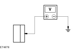
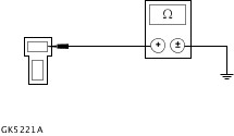
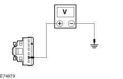
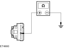
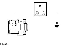
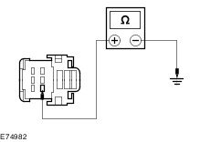
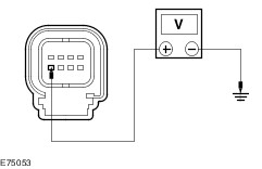
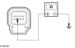
Symptom Chart | Symptom | Possible Sources | Action | | The control illumination is inoperative | * Fuse. * Headlamp switch. * Circuit. | * REFER to the WDS. | | The instrument panel illumination does not dim | * Dimmer switch. | * INSTALL a new headlamp/dimmer switch unit. | | The Instrument cluster illumination is inoperative | * Circuit(s). * Instrument cluster. | * REFER to the WDS. | | The climate control illumination is inoperative | * Circuit(s). * Climate control assembly. | * REFER to the WDS. | | The audio system illumination is inoperative | * Circuit(s). * Audio unit. | * REFER to the WDS. | | The navigation system display module illumination (vehicles with Travel Pilot EX) is inoperative | * Circuit(s). * Navigation system display module. | * REFER to the WDS. | | The navigation system display module illumination (vehicles with DVD Navigation System with Touchscreen) is inoperative | * Circuit(s). * Navigation system display module. | * REFER to the WDS. | | The cigar lighter illumination is inoperative | * Circuit(s). * Cigar lighter. | * | | The hazard switch illumination is inoperative | * Circuit(s). * Hazard switch. | * | | The front seat heater switch(es) illumination is inoperative | * Circuit(s). * Front seat heater switch(es). | * | | The front and rear window defrost switch illumination is inoperative | * Circuit(s). * Rear window defrost switch. | * | | The parking aid switch illumination is inoperative | * Circuit(s). * parking aid switch. | * | | The electronic parking brake switch illumination is inoperative | * Circuit(s). * Electronic parking brake switch. | * | Pinpoint Tests NOTE:Use a digital multimeter for all electrical measurements. | PINPOINT TEST A : THE CIGAR LIGHTER ILLUMINATION IS INOPERATIVE | | TEST CONDITIONS | DETAILS/RESULTS/ACTIONS | | A1: CHECK CIRCUIT CLN17S (BN) FOR VOLTAGE | | | 1 Disconnect Cigar Lighter C2DC07-B. | | | 2 Ignition switch in position II. | | | 3 Make sure that the illumination dimmer switch is in the full illumination position. | | | 4 Place the headlamp switch in the ON position. | | | 5 Measure the voltage between the cigar lighter C2DC07-B pin 1, circuit CLN17S (BN), harness side and ground. | | | Is the voltage greater than 10 volts? Yes No REPAIR the circuit CLN17S (BN) or circuit CLN17G (BN) as necessary. TEST the system for normal operation. | | A2: CHECK CIRCUIT GD138AZ (BK/WH) FOR OPEN | | | 1 Connect Cigar Lighter C2DC07-B. | | | 2 Disconnect Cigar Lighter C2DC07-A. | | | 3 Measure the resistance between the cigar lighter C2DC07-A pin 1, circuit GD138AZ (BK/WH), harness side and ground. | | | Is the resistance less than 5 ohms? Yes INSTALL a new cigar lighter. TEST the system for normal operation. No REPAIR circuit GD138AZ (BK/WH) or circuit GD138AL (BN/WH) as necessary. TEST the system for normal operation. | | PINPOINT TEST B : THE HAZARD SWITCH ILLUMINATION IS INOPERATIVE | | TEST CONDITIONS | DETAILS/RESULTS/ACTIONS | | B1: CHECK CIRCUIT CLS38A (VT/WH) FOR VOLTAGE | | | 1 Disconnect Hazard Switch C2LS32. | | | 2 Ignition switch in position II. | | | 3 Make sure that the illumination dimmer switch is in the full illumination position. | | | 4 Place the headlamp switch in the ON position. | | | 5 Measure the voltage between the hazard switch C2LS32 pin 5, circuit CLS38A (VT/WH), harness side and ground. | | | Is the voltage greater than 10 volts? Yes No REPAIR the circuit. TEST the system for normal operation. | | B2: CHECK CIRCUIT GD133CF (BK) FOR OPEN | | | 1 Ignition switch in position 0. | | | 2 Measure the resistance between hazard switch C2LS32 pin 4, circuit GD133CF (BK), harness side and ground. | | | Is the resistance less than 5 ohms? Yes INSTALL a new hazard switch. TEST the system for normal operation. No REPAIR the circuit GD133CF (BK) or circuit GD133AW (BK) as necessary. TEST the system for normal operation. | | PINPOINT TEST C : THE FRONT SEAT HEATER SWITCH ILLUMINATION IS INOPERATIVE | | TEST CONDITIONS | DETAILS/RESULTS/ACTIONS | | C1: CHECK INOPERATIVE FRONT SEAT HEATER SWITCH FOR VOLTAGE | | | 1 Disconnect Front Seat Heater Switch - C3HS29. | | | 2 Ignition switch in position II. | | | 3 Make sure that the illumination dimmer switch is in the full illumination position. | | | 4 Place the headlamp switch in the ON position. | | | 5 Measure the voltage between the front seat heater switch C3HS29 pin 3, circuit CLN17H (BN), harness side and ground. | | | Is the voltage greater than 10 volts? Yes No REPAIR circuit CLN17H (BN), circuit CLN17J (BN) or circuit CLN17G (BN) as necessary. TEST the system for normal operation. | | C2: CHECK THE FRONT SEAT HEATER SWITCH FOR OPEN | | | 1 Measure the resistance between the front seat heater switch C3HS29 pin 1, circuit GD138AP (BK), harness side and ground. | | | Is the resistance less than 5 ohms? Yes INSTALL a new front seat heater switch. TEST the system for normal operation. No REPAIR circuit GD138AP (BK), circuit GD133AR (BK), circuit GD133CE (BK) or circuit GD133AW (BK) as necessary. TEST the system for normal operation. | | PINPOINT TEST D : THE FRONT AND REAR WINDOW DEFROST SWITCH ILLUMINATION IS INOPERATIVE | | TEST CONDITIONS | DETAILS/RESULTS/ACTIONS | | D1: CHECK THE FRONT AND REAR WINDOW DEFROST SWITCH FOR VOLTAGE | | | 1 Disconnect Rear Window Defrost Switch C2RD09. | | | 2 Ignition switch in position II. | | | 3 Make sure that the illumination dimmer switch is in the full illumination position. | | | 4 Place the headlamp switch in the ON position. | | | 5 Measure the voltage between the rear window defrost switch C2RD09 pin 5, circuit CLN17H (BN), harness side and ground. | | | Is the voltage greater than 10 volts? Yes No REPAIR the circuit CLN17T (BN) or circuit CLN17G (BN) as necessary. TEST the system for normal operation. | | D2: CHECK CIRCUIT GD133BN (BK) FOR OPEN | | | 1 Ignition switch in position 0. | | | 2 Measure the resistance between the rear window defrost switch C2RD09 pin 4, circuit GD133BN (BK), harness side and ground. | | | Is the resistance less than 5 ohms? Yes INSTALL a new rear window defrost switch. TEST the system for normal operation. No REPAIR circuit GD133BN (BK), circuit GD133CH (BK) or circuit GD133AW (BK) as necessary. TEST the system for normal operation. | | PINPOINT TEST E : THE PARKING AID SWITCH ILLUMINATION IS INOPERATIVE | | TEST CONDITIONS | DETAILS/RESULTS/ACTIONS | | E1: CHECK THE PARKING AID SWITCH FOR VOLTAGE | | | 1 Disconnect Parking Aid Switch C2CA15. | | | 2 Ignition switch in position II. | | | 3 Make sure that the illumination dimmer switch is in the full illumination position. | | | 4 Place the headlamp switch in the ON position. | | | 5 Measure the voltage between the parking aid switch C2CA15 pin 5, circuit CLN17U (BN), harness side and ground. | | | Is the voltage greater than 10 volts? Yes No REPAIR the circuit CLN17U (BN) or circuit CLN17G (BN) as necessary. TEST the system for normal operation. | | E2: CHECK CIRCUIT GD133BR (BK) FOR OPEN | | | 1 Ignition switch in position 0. | | | 2 Measure the resistance between the parking aid switch C2CA15 pin 4, circuit GD133BR (BK), harness side and ground. | | | Is the resistance less than 5 ohms? Yes INSTALL a new parking aid switch. TEST the system for normal operation. No REPAIR circuit GD133BR (BK), circuit GD133CH (BK) or circuit GD133AW (BK) as necessary. TEST the system for normal operation. | | PINPOINT TEST F : THE ELECTRONIC PARKING BRAKE SWITCH ILLUMINATION IS INOPERATIVE | | TEST CONDITIONS | DETAILS/RESULTS/ACTIONS | | F1: CHECK THE ELECTRONIC PARKING BRAKE SWITCH FOR VOLTAGE | | | 1 Disconnect Electronic Parking Brake Switch C3CB09. | | | 2 Ignition switch in position II. | | | 3 Make sure that the illumination dimmer switch is in the full illumination position. | | | 4 Place the headlamp switch in the ON position. | | | 5 Measure the voltage between the electronic parking brake switch C3CB09 pin 1, circuit CLN17N (BN), harness side and ground. | | | Is the voltage greater than 10 volts? Yes No REPAIR circuit CLN17N (BN), circuit CLN17J (BN) or circuit CLN17G (BN) as necessary. TEST the system for normal operation. | | F2: CHECK THE ELECTRONIC PARKING BRAKE SWITCH FOR OPEN | | | 1 Measure the resistance between the electronic parking brake switch C3CB09 pin 2, circuit GD138AL (BK), harness side and ground. | | | Is the resistance less than 5 ohms? Yes INSTALL a new electronic parking brake switch. TEST the system for normal operation. No REPAIR circuit GD138AL (BK), circuit GD133AR (BK), circuit GD133CE (BK) or circuit GD133AW (BK) as necessary. TEST the system for normal operation. | |