| PINPOINT TEST C : ONE/SEVERAL TURN SIGNAL LAMPS ARE INOPERATIVE |
| TEST CONDITIONS | DETAILS/RESULTS/ACTIONS |
| C1: DETERMINE THE FAULT CONDITION |
| | 1 Ignition switch in position II. |
| | 2 Vehicles with door locking module: LOCK/UNLOCK the vehicle with both the remote control and the key. |
| | 3 Vehicles with anti-theft alarm system: PRIME the alarm system, then TRIGGER it. |
| | 4 SWITCH the hazard warning lights switch ON/OFF. |
| | 5 Ignition switch in position II. |
| | 6 ACTUATE the left and right-hand turn signal switches. |
| | 7 After each step CHECK the operation of all turn signal lamps. |
| | Is one left-hand turn signal lamp inoperative? Yes - All left-hand turn signal lamps are inoperative: GO to C2. - Left-hand (side) turn signal lamp and left-hand front turn signal lamp are inoperative: LOCATE and REPAIR the break in circuit 31-DA11 (BK) between soldered connection S141 and ground connection G9 using the Wiring Diagrams. CHECK the operation of the system. - Left-hand rear turn signal lamp is inoperative: GO to C5. - Left-hand front turn signal lamp is inoperative: GO to C6. - Left-hand (side) turn signal lamp is inoperative: GO to C7. No - All right-hand turn signal lamps are inoperative: GO to C8. - Right-hand (side) turn signal lamp and right-hand front turn signal lamp are inoperative: LOCATE and REPAIR the break in circuit 31-DA10 (BK) between soldered connection S142 and ground connection G2 using the Wiring Diagrams. CHECK the operation of the system. - Right-hand rear turn signal lamp is inoperative: GO to C14. - Right-hand front turn signal lamp is inoperative: GO to C15. - Right-hand (side) turn signal lamp is inoperative: GO to C16. |
| C2: DETERMINE THE FAULT CONDITION |
| | 1 Check whether the concern arises during normal operation or only in connection with door locking/anti-theft alarm system. |
| | Does the concern only arise during normal operation? Yes No |
| C3: ELIMINATE THE STEERING COLUMN MULTIFUNCTION SWITCH AS THE CAUSE OF THE FAULT |
| | 1 Ignition switch in position 0. |
| | 2 Disconnect Steering column multifunction switch from connector C65a. |
| | 3 Connect a fused jumper wire (10A) to the steering column multifunction switch, connector C65a, between pin 9, circuit 14-LG8 (VT) and pin 5, circuit 49-LG1 (BU), wiring harness side. |
| | 4 Ignition switch in position II. |
| | 5 CHECK left-hand turn signal lamp operation. |
| | Do the turn signal lamps illuminate continuously? Yes RENEW the steering column multifunction switch. CHECK the operation of the system. No LOCATE and RECTIFY the break in the joint voltage supply of the left-hand turn signal lamps, circuit 49-LG1 (BU) between the steering column multifunction switch and soldered connection S17, using the Wiring Diagrams. CHECK the operation of the system. |
| C4: CHECK THE JOINT VOLTAGE SUPPLY (TURN SIGNAL RELAY, CJB) OF THE LEFT-HAND TURN SIGNAL LAMPS FOR OPEN CIRCUIT |
| | 1 Ignition switch in position 0. |
| | 2 Disconnect Left-hand turn signal relay from socket C1261. |
| | 3 Connect a fused jumper wire (10 A) to the left-hand turn signal relay, socket C1261, between pin 3, circuit 29-AA13 (OG/BU), CJB side and pin 5, circuit 49-LG3 (BU), CJB side. |
| | 4 Ignition switch in position II. |
| | 5 CHECK the operation of the left-hand turn signal lamps. |
| | Do the left-hand turn signal lamps illuminate? Yes RENEW the left-hand turn signal relay. CHECK the operation of the system. No LOCATE and RECTIFY the break in the joint voltage supply of the left-hand turn signal lamps, circuit 49-LG3 (BU) between the left-hand turn signal relay and soldered connection S17, using the Wiring Diagrams. CHECK the operation of the system. |
| C5: CHECK THE GROUND CONNECTION TO THE LEFT-HAND REAR LAMP ASSEMBLY FOR OPEN CIRCUIT |
| | 1 Ignition switch in position 0. |
| | 2 SWITCH ON the parking lights. |
| | 3 CHECK the rear left-hand parking lamp. |
| | Is the left-hand parking lamp on? Yes LOCATE and REPAIR the break in circuit 49-LG12 (BU), between soldered connection S17 and the rear lamp assembly, using the Wiring Diagrams. CHECK the rear lamp assembly and RENEW if necessary. CHECK the operation of the system. No LOCATE and RECTIFY the break in circuit 31-LF23 (BK) between the rear lamp assembly and soldered connection S24 using the Wiring Diagrams. CHECK the rear lamp assembly and RENEW if necessary. CHECK the operation of the system. |
| C6: CHECK THE VOLTAGE SUPPLY OF THE FRONT LEFT-HAND TURN SIGNAL LAMP FOR OPEN CIRCUIT |
| | 1 Ignition switch in position 0. |
| | 2 Disconnect left-hand headlamp from connector C157b. |
| | 3 Ignition switch in position II. |
| | 4 SWITCH ON the left-hand turn signal switch. |
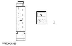
| | 5 Measure the voltage between the left-hand headlamp, connector C157b, pin 2, circuit 49-LG11 (BU/OG), wiring harness side and ground. |
| | Does the meter display fluctuating battery voltage? Yes LOCATE and RECTIFY the break in circuit 31-LG11 (BK) between the headlamp and soldered connection S141 using the Wiring Diagrams. CHECK the headlamp and RENEW if necessary. CHECK the operation of the system. No LOCATE and REPAIR the break in circuit 49-LG11 (BU/OG), between soldered connection S17 and the headlamp, using the Wiring Diagrams. CHECK the operation of the system. |
| C7: CHECK THE VOLTAGE SUPPLY OF THE LEFT-HAND (SIDE) TURN SIGNAL LAMP FOR OPEN CIRCUIT |
| | 1 Ignition switch in position 0. |
| | 2 Disconnect Left-hand (side) turn signal lamp from connector C40. |
| | 3 Ignition switch in position II. |
| | 4 SWITCH ON the left-hand turn signal switch. |
| | 5 Measure the voltage between the left-hand (side) turn signal lamp, connector C40, pin 1, circuit 49-LG13 (BU/RD), wiring harness side and ground. |
| | Does the meter display fluctuating battery voltage? Yes LOCATE and RECTIFY the break in circuit 31-LG13 (BK) between the (side) turn signal lamp and soldered connection S141 using the Wiring Diagrams. If necessary, CHECK and RENEW the (side) turn signal lamp. CHECK the operation of the system. No LOCATE and RECTIFY the break in circuit 49-LG13 (BU/RD) between soldered connection S17 and the (side) turn signal lamp using the Wiring Diagrams. CHECK the operation of the system. |
| C8: DETERMINE THE FAULT CONDITION |
| | 1 Check whether the concern arises during normal operation or only in connection with door locking/anti-theft alarm system. |
| | Does the concern only arise during normal operation? Yes No |
| C9: ELIMINATE THE STEERING COLUMN MULTIFUNCTION SWITCH AS THE CAUSE OF THE FAULT |
| | 1 Ignition switch in position 0. |
| | 2 Disconnect Steering column multifunction switch from connector C65a. |
| | 3 Connect a fused jumper wire (10A) to the steering column multifunction switch, connector C65a, between pin 9, circuit 14-LG8 (VT) and pin 11, circuit 49-LG2 (BU/RD), wiring harness side. |
| | 4 Ignition switch in position II. |
| | 5 CHECK right-hand turn signal lamp operation. |
| | Do the right-hand turn signal lamps illuminate? Yes RENEW the steering column multifunction switch. CHECK the operation of the system. No LOCATE and RECTIFY the break in the joint voltage supply of the right-hand turn signal lamps, circuit 49-LG2 (BU/RD) between the steering column multifunction switch and soldered connection S11, using the Wiring Diagrams. CHECK the operation of the system. |
| C10: CHECK THE VOLTAGE SUPPLY OF THE RIGHT-HAND TURN SIGNAL RELAY - LOAD CURRENT CIRCUIT FOR OPEN CIRCUIT |
| | 1 Ignition switch in position 0. |
| | 2 Disconnect Right-hand turn signal relay from socket C1262. |
| | 3 Ignition switch in position II. |
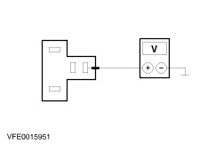
| | 4 Measure the voltage between the right-hand turn signal relay, socket C1262, pin 3, circuit 29-AA13A (OG/BU), CJB side and ground. |
| | Does the meter display battery voltage? Yes No LOCATE and RECTIFY the break in the voltage supply of the right-hand turn signal relay, between the left-hand turn signal relay and the right-hand turn signal relay, using the Wiring Diagrams. CHECK CJB and RENEW if necessary. CHECK the operation of the system. |
| C11: CHECK THE VOLTAGE SUPPLY OF THE RIGHT-HAND TURN SIGNAL RELAY - CONTROL CIRCUIT FOR OPEN CIRCUIT |
| | 1 Ignition switch in position 0. |
| | 2 Measure the voltage between the right-hand turn signal relay, socket C1262, pin 1, circuit 29-AA8A (OG), CJB side and ground. |
| | 3 Ignition switch in position II. |
| | Does the meter display battery voltage? Yes No LOCATE and RECTIFY the break in the voltage supply of the right-hand turn signal relay, between the left-hand turn signal relay and the right-hand turn signal relay, using the Wiring Diagrams. CHECK CJB and RENEW if necessary. CHECK the operation of the system. |
| C12: CHECK THE ACTUATION OF THE RIGHT-HAND TURN SIGNAL RELAY FOR OPEN CIRCUIT |
| | 1 Ignition switch in position 0. |
| | 2 Disconnect Left-hand turn signal relay from socket C1261. |
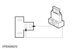
| | 3 Measure the resistance between the left-hand turn signal relay, socket C1261, pin 2, circuit 31S-AA8A (BK/OG)/31S-AA8 (BK/OG), CJB side and the right-hand turn signal relay, socket C1262, pin 2, circuit 31S-AA8A (BK/OG), CJB side. |
| | Is a resistance of less than 2 Ohm registered? Yes No LOCATE and RECTIFY the break in circuit 31S-AA8A (BK/OG) between the left-hand turn signal relay and the right-hand turn signal relay using the Wiring Diagrams. CHECK CJB and RENEW if necessary. CHECK the operation of the system. |
| C13: CHECK THE JOINT VOLTAGE SUPPLY (TURN SIGNAL RELAY, CJB) OF THE RIGHT-HAND TURN SIGNAL LAMPS FOR OPEN CIRCUIT |
| | 1 Connect a fused jumper wire (10 A) to the right-hand turn signal relay, socket C1262, between pin 3, circuit 29-AA13A (OG/BU), CJB side and pin 5, circuit 49-LG4 (BU/RD), CJB side. |
| | 2 Ignition switch in position II. |
| | 3 CHECK the operation of the right-hand turn signal lamps. |
| | Do the right-hand turn signal lamps illuminate? Yes RENEW the right-hand turn signal relay. CHECK the operation of the system. No LOCATE and RECTIFY the break in the joint voltage supply of the right-hand turn signal lamps in circuit 49-LG4 (BU/RD) between the right-hand turn signal relay and soldered connection S11, using the Wiring Diagrams. CHECK the operation of the system. |
| C14: CHECK THE GROUND CONNECTION TO THE RIGHT-HAND REAR LAMP ASSEMBLY FOR OPEN CIRCUIT |
| | 1 Ignition switch in position 0. |
| | 2 SWITCH ON the parking lights. |
| | 3 CHECK the rear parking lamp. |
| | Does the right-hand parking lamp illuminate? Yes LOCATE and REPAIR the break in circuit 49-LG19 (BU/RD), between soldered connection S11 and the rear lamp assembly, using the Wiring Diagrams. CHECK the rear lamp assembly and RENEW if necessary. CHECK the operation of the system. No LOCATE and RECTIFY the break in circuit 31-LF24 (BK), between the rear lamp assembly and ground connection G5 using the Wiring Diagrams. CHECK the rear lamp assembly and RENEW if necessary. CHECK the operation of the system. |
| C15: CHECK THE VOLTAGE SUPPLY OF THE RIGHT-HAND TURN SIGNAL LAMP FOR OPEN CIRCUIT |
| | 1 Ignition switch in position 0. |
| | 2 Disconnect right-hand headlamp from connector C174b. |
| | 3 Ignition switch in position II. |
| | 4 SWITCH ON the right-hand turn signal switch. |
| | 5 Measure the voltage between the right-hand headlamp, connector C174b, pin 2, circuit 49-LG18 (BU), wiring harness side and ground. |
| | Does the meter display fluctuating battery voltage? Yes LOCATE and RECTIFY the break in circuit 31-LG18 (BK) between the headlamp and soldered connection S142 using the Wiring Diagrams. CHECK the headlamp and RENEW if necessary. CHECK the operation of the system. No LOCATE and RECTIFY the break in circuit 49-LG18 (BU) between soldered connection S11 and the headlamp using the Wiring Diagrams. CHECK the operation of the system. |
| C16: CHECK THE VOLTAGE SUPPLY OF THE RIGHT-HAND (SIDE) TURN SIGNAL LAMP FOR OPEN CIRCUIT |
| | 1 Ignition switch in position 0. |
| | 2 Disconnect Right-hand (side) turn signal lamp from connector C39. |
| | 3 Ignition switch in position II. |
| | 4 SWITCH ON the right-hand turn signal switch. |
| | 5 Measure the voltage between the right-hand (side) turn signal lamp, connector C39, pin 1, circuit 49-LG20 (BU/WH), wiring harness side and ground. |
| | Does the meter display fluctuating battery voltage? Yes LOCATE and RECTIFY the break in circuit 31-LG20 (BK) between the (side) turn signal lamp and soldered connection S142 using the Wiring Diagrams. If necessary, CHECK and RENEW the (side) turn signal lamp. CHECK the operation of the system. No LOCATE and RECTIFY the break in circuit 49-LG20 (BU/WH) between soldered connection S11 and the (side) turn signal lamp using the Wiring Diagrams. CHECK the operation of the system. |