
Tempo L4-122 2.0L DSL (1984)
3.
Pivot bearing cage and inner race assembly into position shown in Fig. 23. Align cage windows with outer race lands while pivoting cage, Fig. 24,
then remove from outer race.
4.
To separate inner race from cage, determine cage design and proceed as follows: on cages with six equal windows rotate inner race upward and
remove from cage. On cages with two elongated windows, pivot inner race until it is in position shown in Fig. 23, then align one inner race band
with one elongated window and position race through the window. Rotate inner race upward and remove from cage, Fig. 25.
5.
Reverse procedure to assemble. Refer to Fig. 26 for ball groove and window alignment and proper counterbore positioning.
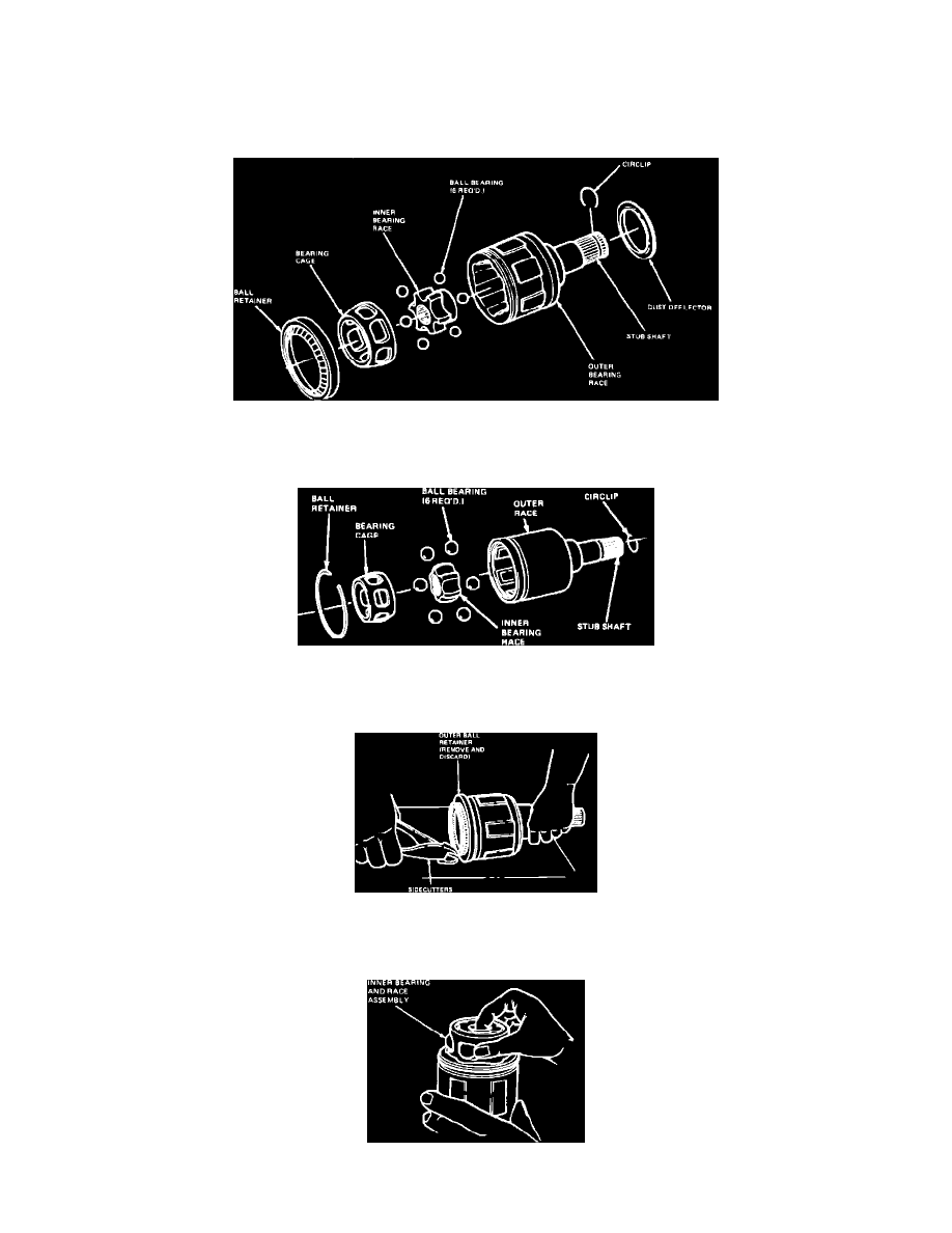
Fig. 27 Inner constant velocity joint assembly. Roll crimp ball retainer type
Roll crimp ball retainer type. Inner C.V. joint
Fig. 28 Inner constant velocity joint assembly. Wire ring ball retainer type
Wire ring ball retainer type. Inner C.V. joint
Fig. 29 Removing inner constant velocity joint outer ball retainer
Removing inner C.V. joint outer ball retainer
Fig. 30 Removing inner constant velocity joint inner race and bearing assembly