| Removal and Installation Special Tool(s) | | Installer, Halfshaft 204-161 (14-041) | | | Separator, Ball Joint 211-020 (13-006) | General Equipment Three leg puller Two leg puller Removal | | -
Loosen the strut and spring assembly top mount nuts by five turns. | | | -
CAUTION:Use a socket to loosen the wheel hub retaining nut to prevent damage. Loosen the wheel hub retaining nut. | | | -
CAUTION:Leave the tie-rod end retaining nut in place to protect the ball joint stud. NOTE:Use a 5 mm Allen key to prevent the ball joint from rotating. Loosen the tie-rod end retaining nut (left-hand side shown). | | | -
CAUTION:Protect the ball joint seal, using a soft cloth to prevent damage. Using the special tool, detach the tie-rod end from the wheel knuckle (left-hand side shown). - Release the tie-rod end.
- Remove the tie-rod end retaining nut.
| | | -
NOTE:Use a T50 Torx driver to prevent the ball joint from rotating. Loosen the lower arm ball joint retaining nut. | | | -
CAUTION:Leave the lower arm ball joint retaining nut in place to protect the ball joint stud. CAUTION:Protect the ball joint seal using a soft cloth to prevent damage. Using a suitable two leg puller, detach the lower arm from the wheel knuckle. - Use a soft faced hammer to strike the lower arm.
- Remove and discard the retaining nut.
| | | -
CAUTION:Secure the halfshaft to prevent damage to the CV joints. The inner CV joint must not be bent more than 18 degrees. The outer CV joint must not be bent more than 45 degrees. | | | -
CAUTION:Secure the halfshaft to prevent damage to the CV joints. The inner CV joint must not be bent more than 18 degrees. The outer CV joint must not be bent more than 45 degrees. CAUTION:Make sure that the inner CV joint boot is not damaged. NOTE:Discard the grease filling. Remove the halfshaft. - Remove and discard the CV joint boot retaining clamps.
| Installation | | -
CAUTION:Make sure that the amount of grease in the CV joint does not exceed 100 grams. Fill the CV joint with grease. | | | -
CAUTION:Secure the halfshaft to prevent damage to the CV joints. The inner CV joint must not be bent more than 18 degrees. The outer CV joint must not be bent more than 45 degrees. Attach the halfshaft to the intermediate shaft. | | | -
CAUTION:Make sure that the inner CV joint boot is not damaged. Install the inner CV joint boot (halfshaft shown removed for clarity). - Use a suitable screwdriver under the boot to allow air to escape.
- Insert the CV joint as far as it will go, then pull it back approximately 20 mm.
| | | -
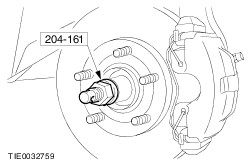
CAUTION:Make sure the halfshaft is completely installed into the wheel hub. Using the special tool, install the halfshaft. | | | -
CAUTION:Protect the heat shield using a soft cloth to prevent damage. NOTE:Use a T50 Torx driver to prevent the ball joint from rotating. NOTE:Install a new lower arm ball joint retaining nut. Attach the lower arm to the wheel knuckle. | | | -
NOTE:Install a new tie-rod end retaining nut. NOTE:Use a 5 mm Allen key to prevent the ball joint from rotating. Attach the tie-rod end to the wheel knuckle. | | | -
WARNING:Install a new wheel hub retaining nut. Failure to follow this instruction may result in personal injury. With the aid of another technician, apply the brakes and preload the wheel bearing by installing the new wheel hub retaining nut. | | | -
Tighten the wheel hub retaining nut. | | | -
Tighten the strut and spring assembly top mount nuts. | | |